Laser bending shaping method and device of light-wall conduit

A bending forming, thin-walled tube technology, applied in laser welding equipment, metal processing equipment, welding equipment, etc., can solve the problem of undiscovered, and achieve the effect of improving fatigue life and small bending radius

Inactive Publication Date: 2008-12-31
SHANDONG UNIV
View PDF1 Cites 14 Cited by
  • Summary
  • Abstract
  • Description
  • Claims
  • Application Information

AI Technical Summary

Problems solved by technology

This forming method uses the compressive stress on the impacted surface to form a convex surface facing the laser beam, which is opposite to the deformation trend of the sheet when it is bent under thermal stress; in addition, no reports have been found that this technology has been successfully used in pipe bending

Method used


Image

  • Laser bending shaping method and device of light-wall conduit
  • Laser bending shaping method and device of light-wall conduit
  • Laser bending shaping method and device of light-wall conduit

Examples


Embodiment Construction

[0030] The details and working conditions of the technical solution proposed by the present invention will be described in detail below in conjunction with the accompanying drawings.

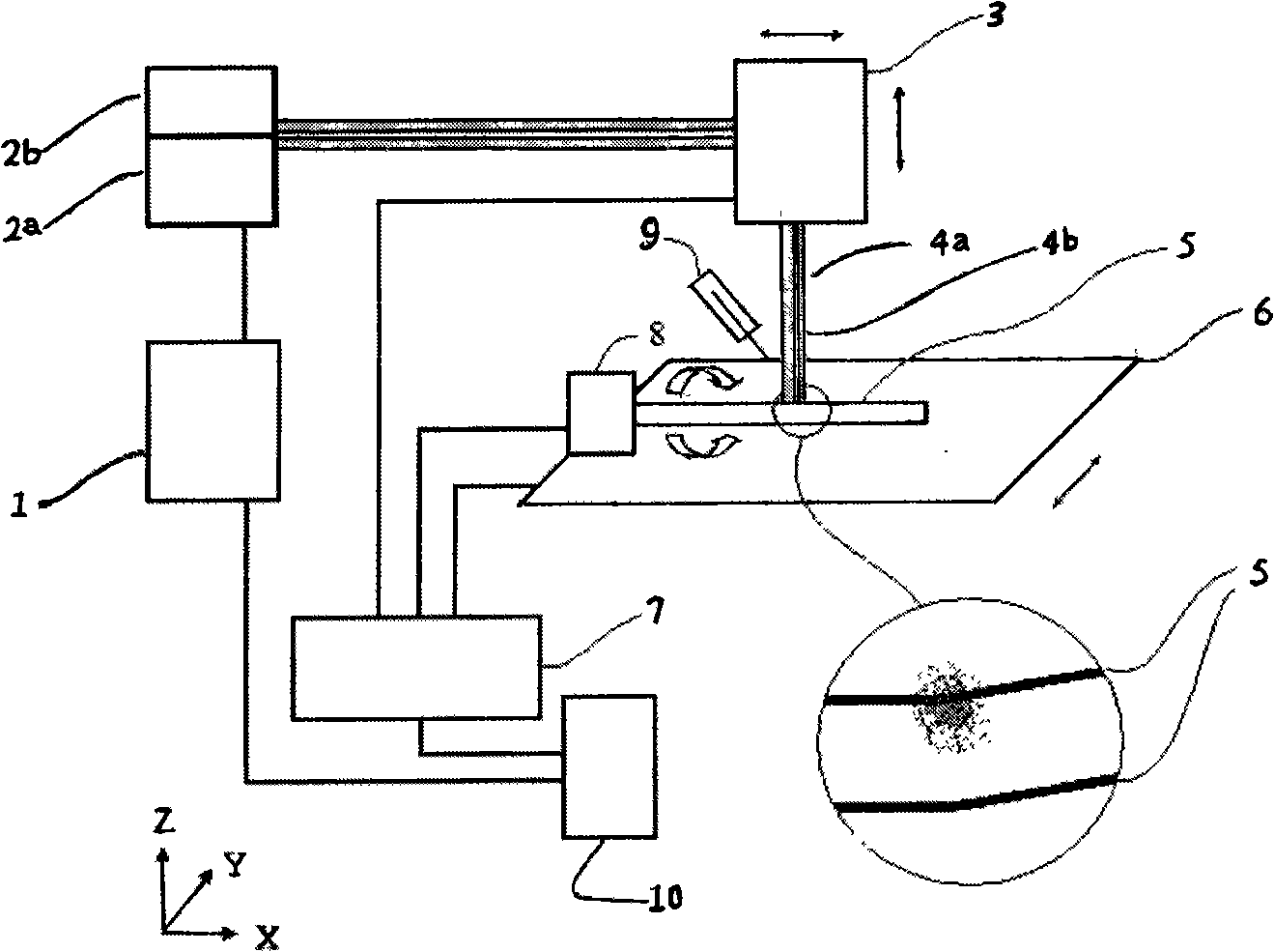
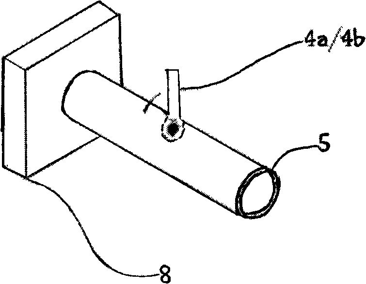
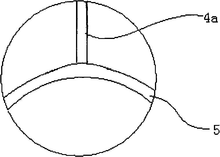
[0031] figure 1 It is a schematic diagram of the thin-walled tube laser bending forming device of the present invention. The laser generator system includes a laser generator control system 1, laser generators 2a and 2b connected in sequence; the laser head system includes a laser head 3 that can move in the X and Z directions, and laser beams 4a and 4b derived from the laser head; the workbench The system includes a workbench 6 that moves along the Y direction, and a small chuck 8 located on the workbench 6 for clamping the pipe 5 and driving the pipe 5 to rotate; it is the motion control system that controls the relative movement of the pipe 5 and the laser beams 4a and 4b 7.

[0032] The thin-walled tube laser bending forming method is that the laser beam emitted by the laser generator 2a i...


PUM

PropertyMeasurementUnit
poweraaaaaaaaaa
thicknessaaaaaaaaaa

Abstract

The invention discloses a laser bending forming method of a thin-walled tube and a special device used for realizing the method. The method adopts two laser beams to act on the thin-walled tube, wherein one laser beam is used for heating the thin-walled tube to soften the thin-walled tube and producing thermal stress along the thickness direction of the tube wall so as to cause the tube to bend and deform; the other laser beam forms a plasma on the surface of the tube, and further bends the thin-walled tube by the shock action produced by the plasma to obtain a fine grain structure. The special device for realizing the laser bending forming method of the thin-walled tube is composed of a laser generator system, a laser head system, a workbench system and a motion control system. By adopting the method, metal and alloy tubes made from steel, aluminum, copper, titanium and the like can be machined, which is a high-flexibility dieless forming technology.

Description

technical field [0001] The invention belongs to the field of advanced manufacturing, and in particular relates to a method for bending and forming a thin-walled tube by laser and a device for realizing the method. Background technique [0002] The traditional bending forming method of thin-walled pipes is mechanical bending, including press bending, roll bending, push bending, and winding bending. During the mechanical bending process, the outer wall of the pipe deformation zone will become thinner due to tension, and dents or cracks will appear, resulting in tension damage; the inner wall of the deformation zone will become thicker and wrinkle; Ovalization and bending springback occur. These defects bring difficulties to the control of the bending process and the precision of the bending. [0003] Liu Ren and Ji Zhong's academic paper "Laser Forming of Sheet Metal and Its Research Progress" (Forging Equipment and Manufacturing Technology, 2004, (3)) introduced the technol...

Claims


Application Information

Patent Timeline
Patent Type & Authority Applications(China)
IPC IPC(8): B23K26/00B23K26/18B23K26/14B23K26/08B23K26/146
Inventor 季忠刘韧王巍刘晓军杨丹丹刘晶林乐嘉
Owner SHANDONG UNIV
Why Eureka
Try Eureka