Automobile electric control unit calibration system and method based on ASAP standard

A technology for automotive electronic control units and calibration systems, applied in the direction of electrical program control, comprehensive factory control, comprehensive factory control, etc., can solve problems such as irregular data storage methods and interface mismatches, achieve good versatility, and solve interface inconsistencies Match and guarantee the effect of product quality

Inactive Publication Date: 2008-12-31
CHONGQING UNIV OF POSTS & TELECOMM
3 Cites 40 Cited by

AI-Extracted Technical Summary

Problems solved by technology

[0006] In order to solve the problems of interface mismatch between controllers and calibration systems provided by different manufacturers and non-standard data storag...

Abstract

The invention provides an automobile electronic control unit marking system and a method on the basis of ASAP standard, relating to the field of automobile electronic control technique. The ASAP standard is adopted to describe the marking/monitoring data property; the map file of an ASAP editing module on the basis of ECU is used for generating an ASAP database which is used for describing the marking/monitoring data property; an upper host machine configures the working environment according to the ASAP database, uses a CAN bus to carry out communication with the ECU by an XCP protocol, emits a marking control command, receives the ECU monitoring data, carries out the display, storage and analysis of the monitoring data, and realizes the marking and the monitoring to ECU parameters. The method of the invention overcomes the defects that the existing marking method has nonstandard data management, is difficult to be adapted to the changes of the ECU types and the communication interfaces of the ECU and has poor generalization, and improves the generalization and the adaptability of the marking system, thus improving the efficiency of the marking operation.

Application Domain

Total factory controlProgramme total factory control

Technology Topic

Communication interfaceElectronic control unit +7

Image

  • Automobile electric control unit calibration system and method based on ASAP standard
  • Automobile electric control unit calibration system and method based on ASAP standard
  • Automobile electric control unit calibration system and method based on ASAP standard

Examples

  • Experimental program(1)

Example Embodiment

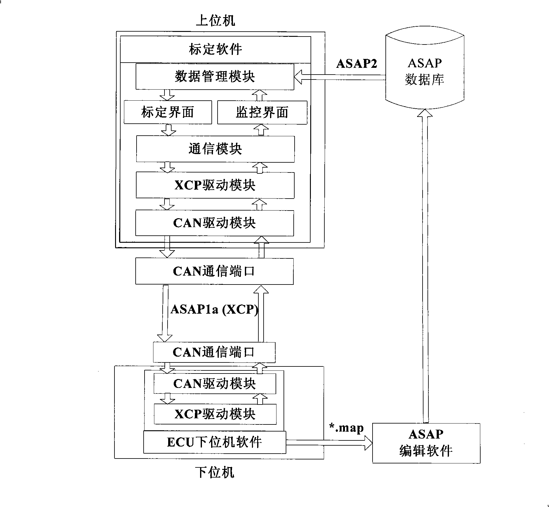
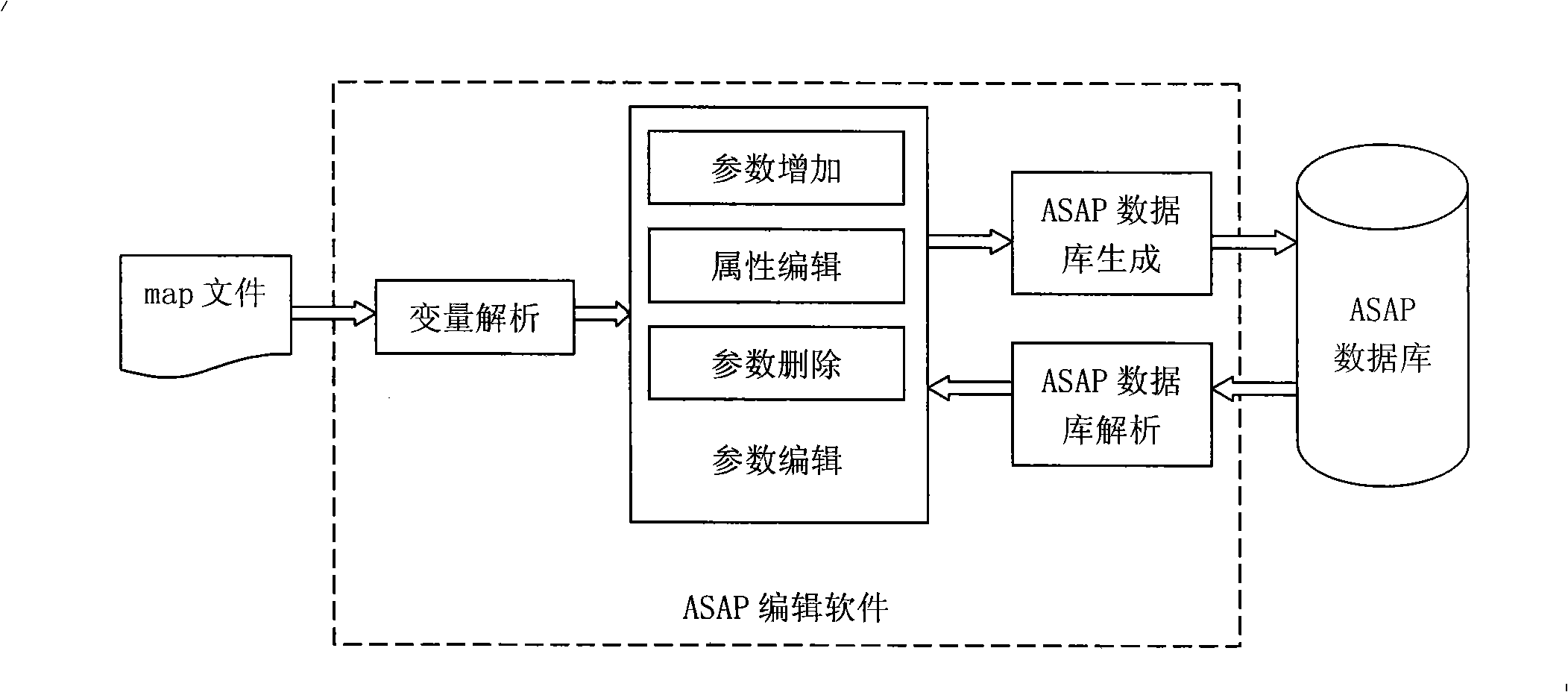
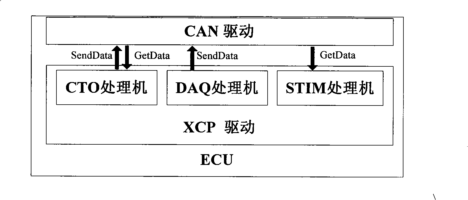
[0020] The ASAP standard is a set of matching calibration specifications. The ASAP standard is mainly composed of three parts, namely ASAP1, ASAP2, and ASAP3. As the interface standard between the application layer and the control device, the ASAP1 part defines the physical and logical connection between the application system and the ECU, and realizes the unified management of the upper and lower communication of the matching calibration system. XCP is a kind of ASAP1a. The ASAP2 part realizes unified management of all calibration data, monitoring data, interface information, etc., standard and standardized description of ECU functions, interfaces and calibration information, and the ASAP description file (*.a21 file) generated according to this standard is used as calibration The database of the system. The ASAP2 standard uses the ASAP2 meta-language A2ML (ASAP2Meta Language), and uses structured text to describe monitoring and calibration parameters and their interface information. Each parameter is represented by a structure, and each attribute of the parameter is marked by keywords in the structure. The ASAP database is a platform for data exchange between various devices included in ASAP1. This enables a calibration system that conforms to the ASAP2 standard to process the ECU interface information provided by different manufacturers in the same way, and can compare ECUs provided by different manufacturers. Carry out calibration, so it has versatility.
[0021] The specific embodiments of the present invention will be described below with reference to the drawings and specific examples.
[0022] Such as figure 1 As shown, the calibration system hardware of the present invention consists of a calibration computer (upper computer) with CAN interface function and one or more automotive electronic control units (lower computers) with CAN bus communication ports, and they are connected via CAN bus.
[0023]The system consists of the upper computer calibration control module, the ECU lower computer calibration module and the ASAP editing module. The upper computer calibration control module configures the working environment of the calibration system according to the ASAP database file, and implements communication with the ECU through the CAN bus following the XCP protocol, issuing calibration control commands, receiving ECU monitoring data, and realizing the calibration and monitoring of the ECU. Specifically, it is composed of user interface control module, data management module, communication module, XCP drive module and CAN drive module. Among them, the user interface control module controls the display interface to simultaneously display the calibration interface and the monitoring interface on separate screens. The calibration interface is used as the man-machine interface for the calibration operation to realize the parameter calibration operation, and the monitoring interface displays the monitoring data of the ECU; the data management module analyzes the ASAP database Calibration, measurement data and interface information, configuration parameter attributes for user interface display and management; communication module encapsulates XCP drive module and CAN drive module to provide communication with ECU for user interface, realize calibration parameter issuance and monitoring parameter reception And other control functions. In addition to the ECU work control module, the ECU lower computer calibration module also includes CAN drive and XCP drive modules, which receive the calibration and upload commands from the upper computer calibration control module to complete the calibration of ECU control parameters and the collection and upload of monitoring parameters. The ASAP editing module analyzes and edits different types of ECU variables and their stored mapping files (map files) during the compilation and linking process of the ECU underlying software provided by different manufacturers, and generates description calibration data, monitoring data and interface information The standardized ASAP database file for the upper computer calibration control module to configure its working environment, thereby linking the ECU control program with the calibration program.
[0024] Such as figure 2 Shown is the module functional structure diagram of the ASAP editing module, which mainly includes four functional modules: map file variable analysis, parameter editing (add, delete, attribute editing), ASAP database analysis, and ASAP database generation.
[0025] The map file variable analysis module is suitable for the first generation of ASAP database from the map file. It reads the variable name, address, data type, array size and other basic information of all variables in the calibration module of the lower computer from the map file, and writes it into a parameter list . The parameter editing module adds, deletes, and edits the parameter attributes of the calibration and monitoring parameters in the list according to the control commands of the host computer calibration module, determines the parameters that need to be calibrated/monitored, and supplements the parameter attributes that cannot be expressed in the map file, such as accuracy , Value range, expression method, etc., to obtain detailed information of calibration and monitoring parameters.
[0026] The ASAP database generation module uses A2ML syntax to express the edited parameters and their attributes in the parameter list into structured text to generate the ASAP database. The ASAP database analysis module is suitable for the existing ASAP database but needs to be modified. In this module, it matches according to the A2ML language grammatical structure, parses the existing ASAP database file, obtains the parameter information and writes it as described above The parameter list is for editing by the editing module and updating the ASAP database.
[0027] Such as image 3 Shown is a schematic diagram of the ECU lower-level computer calibration module structure. The lower-level computer calibration module is mainly composed of a CAN drive module and an XCP drive module. The XCP drive module follows the XCP protocol, communicates with the host computer calibration module, receives and executes the control parameter calibration instructions and monitoring parameter upload instructions issued by the host computer calibration module, so as to achieve the calibration of ECU control parameters and the upload of monitoring parameters. The CAN driver module encapsulates the CAN communication protocol and provides a calling interface for the XCP driver. XCP driver is the key to realize the function of the lower computer calibration software. It is composed of XCP CTO (Command Transfer Object) processor, DAQ (Data Acquisition) processor, and STIM (Data Stimulation, data activation) processor. . The CTO processor starts to run after the ECU is initialized, monitors the XCP session commands on the CAN network, receives and parses the XCP commands of the host computer calibration software and executes them, and at the same time sends a response to the host computer calibration software; if the host computer calibration software XCP commands If a DAQ operation is required, the operation command is passed to the STIM processor, which is executed by the STIM processor, configures DAQ parameters and controls its operation. The DAQ processor classifies the ECU monitoring parameters according to the specified cycle according to the environmental parameters configured by the STIM processor, and sends the monitoring data to the upper computer according to the set cycle.
[0028] Such as Figure 4 Shown is the control flow of the upper computer calibration module, including the following steps:
[0029] (1) The host computer calibration module first starts the data management module, loads the ASAP database corresponding to the target ECU, and the ASAP parsing module analyzes the attributes of the calibration and monitoring parameters; (2) The initialization submodule configures environmental parameters according to the information in the ASAP database, Including XCP and CAN communication parameters, establish a connection with the target ECU device and configure the DAQ data acquisition method of the lower computer; (3) The upper computer calibration module waits for the user to operate, if the user modifies the calibration parameters in the calibration interface, call the parameter calibration process to send to the ECU The new value of the parameter and its address are used to calibrate and modify the control parameters of the specified address; (4) If the user starts/stops the DAQ data transmission on the monitoring interface, the corresponding STIM control command is sent to the ECU and monitored by the parameters Process to realize the monitoring function.
[0030] Such as Figure 5 Shown is the host computer parameter calibration process. The host computer parameter calibration module modifies the parameters in the ECU, including the following steps: (1) According to the user-calibrated parameter variable name in the interface, check the address of the variable in the ASAP database, Information such as address offset and conversion method, and convert the parameters according to the conversion method; (2) Call the set data pointer command SET_MTA in XCP to determine the starting address of the target parameter to be calibrated in the ECU memory; (3) Call the XCP command DNLOAD to deliver the address segment length information and calibration data that need to be calibrated to the ECU; (4) After the calibration is successful, modify the value of the parameter in the calibration data buffer of the host computer at the same time to complete the calibration of the control parameters.
[0031] Such as Figure 6 Shown is the upper computer parameter monitoring flowchart. The upper computer monitoring module receives the DAQ data uploaded by the ECU and sends it to the monitoring interface for display. It includes the following steps: (1) Read the data uploaded by the ECU to obtain the DAQ frame; (2) Analyze the DAQ Frame, get the monitoring data; (3) Store the monitoring data in the upper computer monitoring data buffer; (4) Take out the monitoring data from the monitoring data buffer and display it on the interface; (5) Wait for the DAQ data arrival message, ready to receive the next DAQ data frame.
[0032] The calibration system of the invention is applicable to XCP protocol 1.0 and ASAP2 protocol 1.51 and other versions, standardizes data management and interfaces, improves the versatility and adaptability of the calibration system, and improves the efficiency of the calibration work.

PUM

no PUM

Description & Claims & Application Information

We can also present the details of the Description, Claims and Application information to help users get a comprehensive understanding of the technical details of the patent, such as background art, summary of invention, brief description of drawings, description of embodiments, and other original content. On the other hand, users can also determine the specific scope of protection of the technology through the list of claims; as well as understand the changes in the life cycle of the technology with the presentation of the patent timeline. Login to view more.

Similar technology patents

Method for carrying out cluster management on network equipment based on SNMP protocol

InactiveCN1885858ASave public network ip address resourcesVersatile
Owner:CHINA GREATWALL TECH GRP CO LTD

Servo hydraulic transmission mechanism

InactiveCN101839258AAvoid hidden dangers of mechanical failureVersatile
Owner:宋家骏

Classification and recommendation of technical efficacy words

  • Versatile

Multi-bus automobile communication control module based on TCN

ActiveCN1889494AaccelerateVersatile
Owner:ZHUZHOU CSR TIMES ELECTRIC CO LTD

Variable capacity multi-cylinder rotary compressor and its running method

InactiveCN1955476Alow costVersatile
Owner:LG ELECTRONICS (TIANJIN) APPLIANCES CO LTD

Blood cell analyzer and analysis method

InactiveCN101407759AVersatileReagent saving
Owner:BEIJING INSTITUTE OF TECHNOLOGYGY
Why Eureka
Try Eureka