
Glass fibre reinforced plastic concrete reinforced pipe with steel faucet

A technology for reinforced concrete pipes and concrete pipes, which is applied in the direction of pipes, rigid pipes, pipe connection arrangements, etc. It can solve the problems of micro-cracks on the outer wall of the protective layer, increase the cost of raw materials, and affect the aesthetics of pipes, etc., and achieve the cost of raw materials and construction costs. Low cost, saving raw material cost, good joint water sealing effect

Inactive Publication Date: 2009-01-14
天津万联管道技术开发有限公司
View PDF0 Cites 1 Cited by
  • Summary
  • Abstract
  • Description
  • Claims
  • Application Information

AI Technical Summary

Problems solved by technology

Although these pipes can achieve the purpose of water delivery to a certain extent, there are some technical defects: 1. Poor impermeability; 2. Poor corrosion resistance; 3. High repair and maintenance costs; 4. The outer wall of the pipe Micro-cracks are prone to appear after forming, which increases the repair cost and affects the aesthetics of the overall pipe; 5. The weight of the pipe is heavy, and the transportation and construction costs are high
[0003] After searching, a PCCP pipe was found. On the basis of the existing concrete pipe, a thin steel cylinder was coaxially embedded in the pipe core, and the two ends of the thin steel cylinder were welded on the socket and the socket. Although it can It meets the requirements of good impermeability, but today, with the rising steel, it not only increases the cost of raw materials, but also makes the manufacturing process very complicated, and as the pipeline is laid underground for a long time, its steel cylinder will also Corrosion occurs, resulting in high maintenance costs, and the outer wall of the PCCP pipe is a cement mortar protective layer. After forming, due to the influence of air drying and hoisting, the outer wall of the protective layer is prone to micro cracks, and the pipe is heavy. Transportation and construction higher cost

Method used


Image

  • Glass fibre reinforced plastic concrete reinforced pipe with steel faucet
  • Glass fibre reinforced plastic concrete reinforced pipe with steel faucet
  • Glass fibre reinforced plastic concrete reinforced pipe with steel faucet

Examples


Embodiment Construction

[0017] The present invention will be further described in detail below through the specific examples, the following examples are only descriptive, not restrictive, and cannot limit the protection scope of the present invention with this.

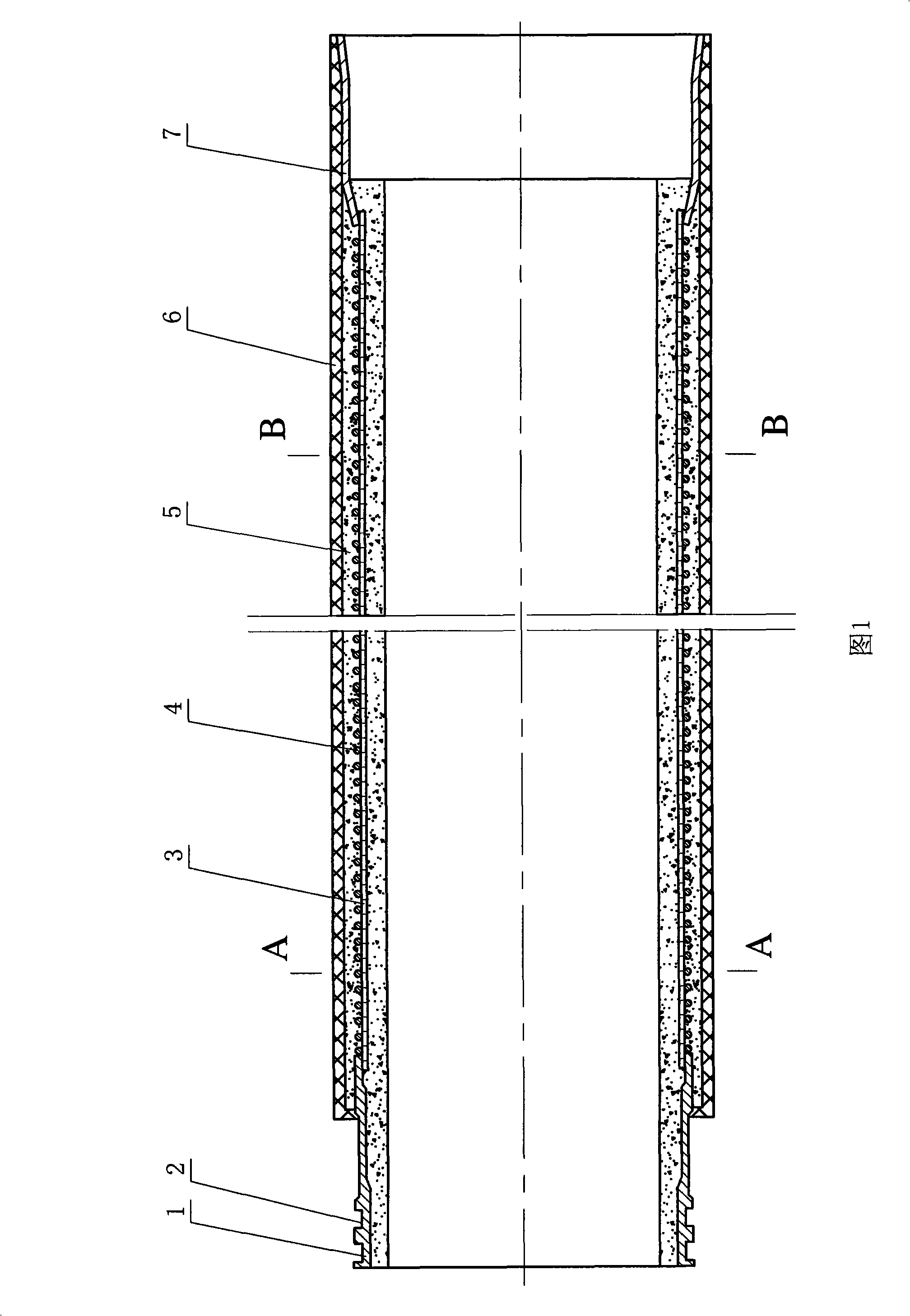
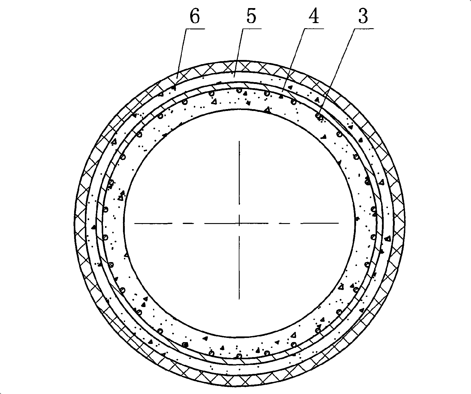
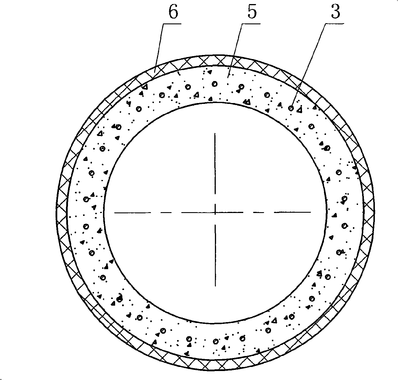
[0018] This steel socket socket FRP reinforced concrete pipe is composed of socket 7, socket 1 and concrete pipe core 5. The socket and socket are respectively fixed on the two ends of the concrete pipe core. The concrete pipe core is coaxially embedded with a cylindrical Steel skeleton, the cylindrical steel skeleton is composed of longitudinal steel bars 3 and circumferential steel bars 4, and the two ends of the cylindrical steel skeleton are fixed on the socket and the socket, and the outer wall of the socket is radially formed with 1-3 grooves 2 (shown as 2 grooves in the accompanying drawings of this embodiment), wherein the outer wall of the concrete tube core is coaxially fixed with a glass fiber reinforced plastic sheath 6.

[0019]...


PUM


Abstract

The invention relates to a steel mouthing socket glass steel reinforced concrete pipe which is composed of a mouthing, a socket, and a concrete pipe core; the mouthing and the socket are fixedly arranged at two ends of the concrete pipe core respectively; the concrete pipe core is coaxially embedded with a cylindrical steel skeleton; the two ends of the cylindrical steel skeleton are fixedly arranged on the mouthing and the socket, wherein, the outer wall of the concrete pipe core is coaxially and fixedly provided with a fiberglass sheath. The concrete pipe has the advantages of simple structure, scientific and rational design, good durability, corrosion resistance, impermeability, uneven sedimentation resistance, low raw material cost and low construction cost, simple construction process and easy maintenance, and is a steel mouthing socket glass steel reinforced concrete pipe with higher innovation.

Description

technical field [0001] The invention relates to a concrete pipe, in particular to a glass reinforced concrete pipe with a steel socket socket. Background technique [0002] Among the various concrete water pipes currently used in my country, there are mainly self-stressed concrete pipes, prestressed concrete pipes and other concrete drainage pipes with various interface forms according to categories, which are mainly used in municipal, water conservancy, road and bridge, urban water supply and drainage systems, Industrial water pipelines, farmland irrigation, factory pipe networks and deep-covered soil culvert pipes, etc. Although these pipes can achieve the purpose of water delivery to a certain extent, there are some technical defects: 1. Poor impermeability; 2. Poor corrosion resistance; 3. High repair and maintenance costs; 4. The outer wall of the pipe Microcracks are prone to appear after forming, which increases the repair cost and affects the aesthetics of the overal...

Claims


Application Information

Patent Timeline
Patent Type & Authority Applications(China)
IPC IPC(8): F16L9/14F16L47/06
Inventor 赵斌张亮
Owner 天津万联管道技术开发有限公司
Learn More