Hydraulic sliding valve mechanism containing force balance flow path

A technology of hydraulic slide valve and force balance, which is applied in the direction of valve energy absorption devices, valve details, multi-way valves, etc., which can solve the problems of reduced flow capacity, poor controllability, and difficulty in manufacturing Requirements for external control power, improved power range, simple structure

A technology of hydraulic slide valve and force balance, which is applied in the direction of valve energy absorption devices, valve details, multi-way valves, etc., which can solve the problems of reduced flow capacity, poor controllability, and difficulty in manufacturing Requirements for external control power, improved power range, simple structure

CN101354089AInactive Publication Date: 2009-01-28TAIYUAN UNIV OF TECH

Image

  • Hydraulic sliding valve mechanism containing force balance flow path
  • Hydraulic sliding valve mechanism containing force balance flow path
  • Hydraulic sliding valve mechanism containing force balance flow path

Examples


Embodiment 1

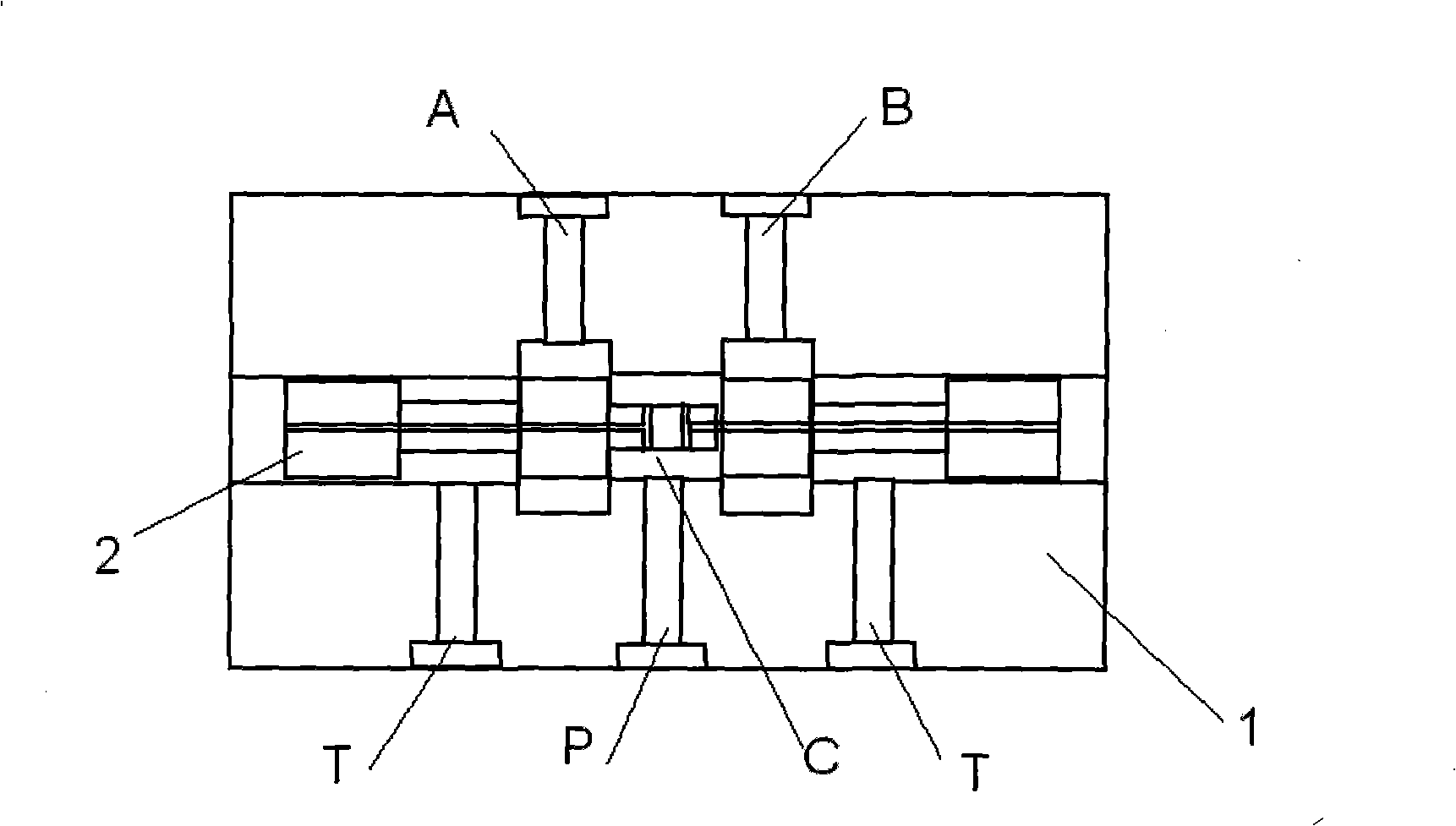
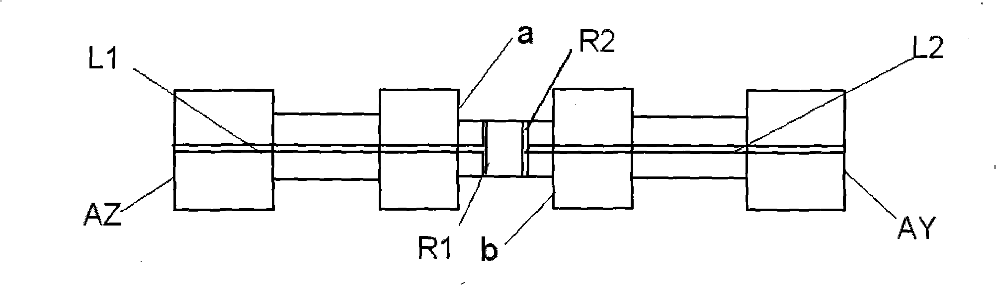
[0019] The first embodiment of the hydraulic sliding valve mechanism of the present invention that contains force balance channels, such as figure 1 , figure 2 As shown, it mainly includes a valve body 1 and two spools 2, adopting a four-step structure, and the valve body is processed with an oil inlet channel P, a first oil outlet channel A, a second oil outlet channel B, The oil return channel T, the external pressure oil is introduced into the inlet cavity C through the oil inlet channel P, the first oil outlet channel A communicates with the inlet cavity C through the throttling edge I a, and the second oil outlet channel B It communicates with the inlet cavity C through the throttling edge IIb, and its structural improvement is that the two spools 2 are processed with a pressure balance flow channel I L1 and a pressure balance flow channel II L2, and the pressure balance flow channel I L1 passes through the small hole I R1 Introduce the pressure oil near the throttle ed...

Embodiment 2

[0021] The second embodiment of the hydraulic sliding valve mechanism of the present invention containing force balance flow passage, such as image 3 As shown, its composition is the same as that of Embodiment 1, and its slide valve core adopts a four-step structure, and its structural relationship is that the pressure oil in the pressure balance channel I L1 is drawn from the end face where the throttle edge I a is located, and the pressure balance flow The pressure oil of channel IIL2 is drawn from the end face where the throttling edge IIb is located.

Embodiment 3

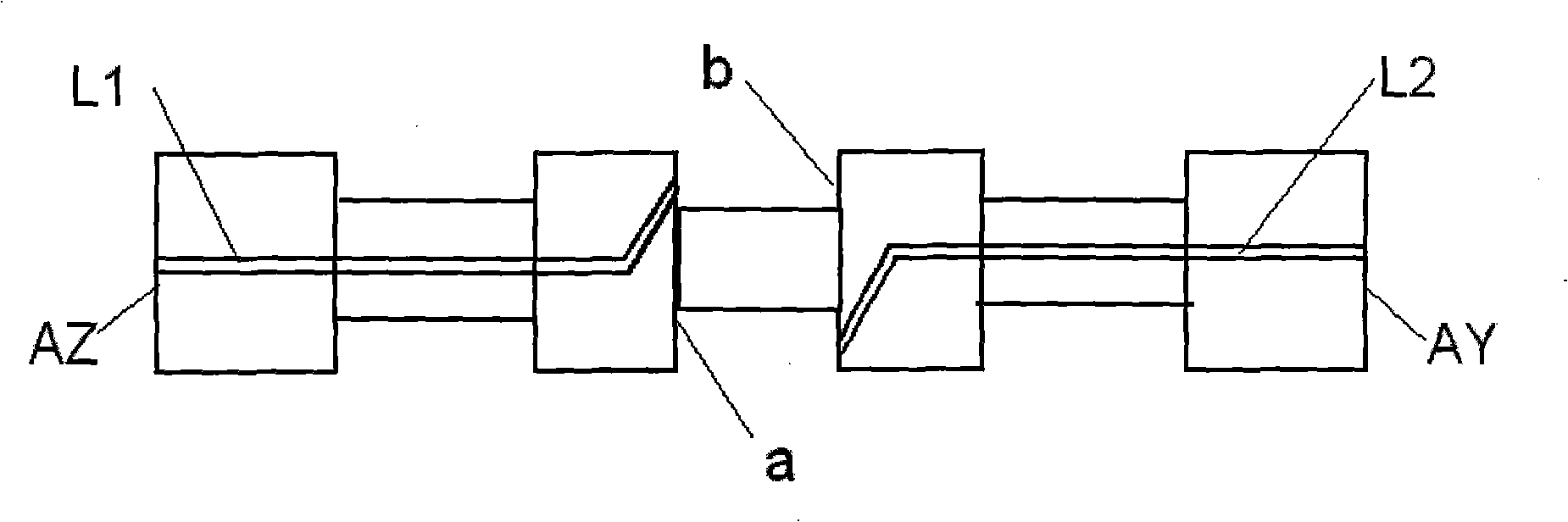
[0023] The third embodiment of the hydraulic sliding valve mechanism of the present invention that contains force balance channels, such as Figure 4 , Figure 5 As shown, its composition is the same as Example 1, the difference is that the slide valve core 2 adopts a two-step structure.


PUM


Abstract

The invention discloses a hydraulic slide valve mechanism provided with a force-balance channel. The mechanism is characterized in that: a pressure-balance channel I is arranged on a slide valve core and leads pressure oil close to the I surface of a throttle side in an inlet square-cavity to the left end surface of the slide valve by a keyhole I; the valve core is provided with a pressure-balance channel II that leads pressure oil close to the II surface of the throttle side in the inlet square-cavity to the right end surface of the slide valve by a keyhole II. By the balance of the internal hydraulic pressure of the valve core, the hydraulic force compensation mechanism provided with the pressure-balance channel reduces the effect of hydraulic thrust and the requirements of the slide valve on external control power, improves the power range which can be controlled by a directly driving hydraulic slide valve and mainly aims at laying a foundation for the realization of direct control over a hydraulic valve with large latus rectum and large flow and being capable of directly controlling the hydraulic valve of large power, thereby broadening the application range of the hydraulic slide valve mechanism.

Description

technical field [0001] The invention relates to a hydraulic sliding valve mechanism with a balanced flow channel in the field of hydraulic technology, in particular to a hydraulic sliding valve mechanism with a force balanced flow channel for controlling the magnitude and direction of flow entering a hydraulic actuator. Background technique [0002] Hydraulic slide valve is one of the most important control components in hydraulic control technology. It has two-position, three-position, two-way, three-way, four-way and other forms in structure. Its function is to control the flow direction of fluid. and the amount of traffic passing through. However, when the liquid flow passes through the valve port of the slide valve, the momentum of the liquid will change, causing the pressure distribution on the step of the valve core to change, thereby generating an additional forceโ€”the hydraulic force acts on the valve core, Existing research results have confirmed that the magnitude ...

Claims


Application Information

Patent Timeline
28 Jan 2009
Publication
CN101354089A
IPC
F16K11/10; F16K47/04; F16K31/06; F15B13/044
Inventors
ๆƒ้พ™; ้™ˆ้’