Spectrometer and method for correcting the same

A spectrometer and light source technology, applied in the field of spectrometers, can solve problems such as small dynamic range, unstable response of photomultiplier tubes, and poor measurement accuracy.

Inactive Publication Date: 2009-01-28
HANGZHOU EVERFINE PHOTO E INFO
View PDF1 Cites 46 Cited by
  • Summary
  • Abstract
  • Description
  • Claims
  • Application Information

AI Technical Summary

Problems solved by technology

[0005] The purpose of the present invention is to address the above problems, to provide a spectrometer with reasonable design, simple structure, which can effectively improve the working stability, linearly correct the absolute sensitivity of the photomultiplier tube, and then improve the measurement a

Method used


Image

  • Spectrometer and method for correcting the same
  • Spectrometer and method for correcting the same
  • Spectrometer and method for correcting the same

Examples


Embodiment 1

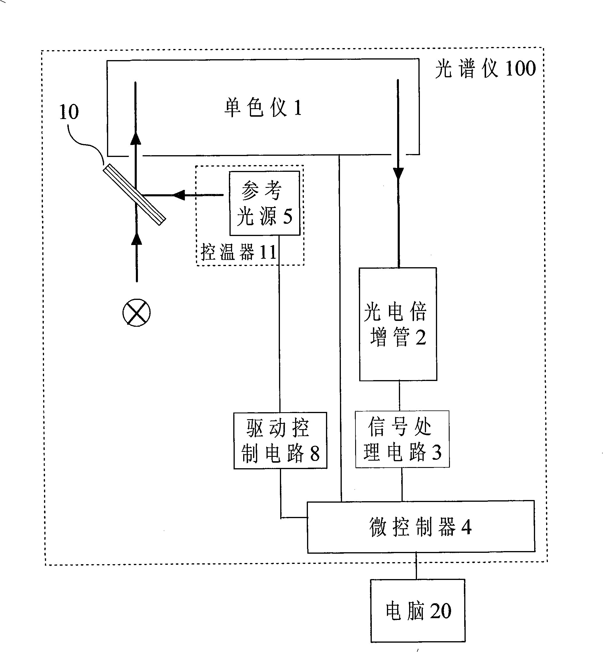
[0032] Such as figure 1 As shown, the spectrometer is composed of monochromator 1, photomultiplier tube 2, signal processing circuit 3, microcontroller 4 and reference light source 5 and other components. The dotted line part in the figure is the structure of the spectrometer 100 . The monochromator 1 divides the light to be measured introduced by the incident slit into monochromatic light, and the photomultiplier tube 2 senses the monochromatic light emitted by the monochromator 1 to measure the spectral power distribution of the light to be measured, and the photomultiplier tube 2 passes the signal processing The circuit 3 is electrically connected to the microcontroller 4 , and the reference light source 5 can emit reference light to illuminate the incident slit of the monochromator 1 .

[0033] The present invention specifically includes a monochromator 1 for separating the measured light into monochromatic light, a photomultiplier tube 2 for receiving monochromatic light...

Embodiment 2

[0043] Such as Figure 4 As shown, another embodiment of the spectrometer is: on the basis of the above-mentioned spectrometer structure, a reference detector 6 for receiving reference light is added, and its position is arranged on the opposite side of the reference light source 5, and the reference light source 5 emits reference light. Irradiated on the reference detector 6 and the incident slit of the monochromator 1 respectively, the response signal size of the reference detector 6 to the reference light is proportional to the intensity of the reference light, and this signal is used as the reference signal (replacing the driving current of the reference light source ), combined with the response signal of the photomultiplier tube 2 to the reference light, the absolute sensitivity of the photomultiplier tube 2 is corrected.

[0044] More specifically, the reference detector 6 is a silicon photodiode, and its electrical signal is sent to the microcontroller 4 through a sign...


PUM


Abstract

The invention relates to an optical spectrometer and a calibration method thereof. The optical spectrometer comprises a monochromator used for dividing the measured light into monochromatic lights, a photomultiplier used for receiving the monochromatic lights; the monochromator and the photomultiplier are optically connected. The photomultiplier is electrically connected with a microcontroller by a signal processing circuit. The optical spectrometer is characterized by further comprising a reference light source used for creating reference light; the reference light source which is alight-emitting diode is connected with the micro-controller. Compared with the prior art, the optical spectrometer and the calibration method thereof have the advantages as follows: 1. reasonable design, simple structure and large measuring dynamic range are ensured; 2. the absolute sensitivity of the photomultiplier is reasonably calibrated, therefore, the response linearity of the optical spectrometer is good; 3. thermostatic control is carried out to a reference detector, the reference light source and the photomultiplier, thus effectively enhancing the work stability of the optical spectrometer; and 4. the performance of the optical spectrometer is substantially enhanced under the condition that a small amount of cost is increased.

Description

technical field [0001] The invention relates to the field of spectral radiation testing, in particular to a spectrometer capable of correcting the absolute sensitivity of a photomultiplier tube within a large dynamic range and a calibration method thereof. Background technique [0002] The principle of the spectrometer to measure spectral radiation is generally: the measured incident light is irradiated in the incident slit of the monochromator, and the monochromator divides the measured light into monochromatic light within a certain wavelength range, and then the monochromatic light within a certain bandwidth The light is sequentially emitted from the exit slit and irradiated on the photoelectric sensor, and the signal generated by the photoelectric sensor is proportional to the intensity of the light irradiated on it. By comparing this signal with the signal of a standard light source with known spectral power distribution, the spectral power distribution of the measured ...

Claims


Application Information

Patent Timeline
IPC IPC(8): G01J3/28G01J3/02
Inventor 潘建根沈海平
Owner HANGZHOU EVERFINE PHOTO E INFO
Why Eureka
Try Eureka