Cable-type composite printed wiring board, cable component, and electronic device

A wiring circuit board, combined printing technology, applied in the directions of printed circuit components, printed circuits, printed circuits, etc., can solve the problems of unstable high-frequency characteristics, inability to perform parallel movement, and unstable electrical connection.

Inactive Publication Date: 2009-01-28
SHARP KK
View PDF4 Cites 4 Cited by
  • Summary
  • Abstract
  • Description
  • Claims
  • Application Information

AI Technical Summary

Problems solved by technology

[0033] When connecting with a wire with a connector, a coaxial wire with a connector (existing example 2), or a flexible circuit board with a connector (existing example 3), the electrical connection is made by the contact of the connector, so the electrical connection is not Stability, reliability issues
[0034] Moreover, since the connection is performed by mechanically fitting the connector, there is a problem of unstable connection strength
Also, since the connector is mounted on the printed circuit board, the printed circuit board needs to occupy an area, and there is a problem that the surface area of ​​the printed circuit board cannot be fully utilized.
[0035] In the case of connecting with a flexible circuit board with a connector or a rigid-flex multilayer printed wiring circuit board (existing example 4), the pattern width and pattern spacing deviations occur in the etching process to form the flexible circuit board, so there is a problem with high-frequency characteristics. stability problem
Moreover, since the entire periphery of the signal pattern cannot be surrounded by the shielding pattern structurally, unwanted radiation cannot be shielded, and there are problems in electromagnetic shielding performance
Also, since the inner layer structure of the rigid part and the structure of the flexible part are formed with an integrated conductor or insulator, there is a problem that the electrical performance and mechanical performance in the lead part cannot be given priority.
In addition, due to the formation of planar flexible joints, there are configurations that cannot be moved in parallel and configurations that cannot be moved by twisting

Method used


Image

  • Cable-type composite printed wiring board, cable component, and electronic device
  • Cable-type composite printed wiring board, cable component, and electronic device
  • Cable-type composite printed wiring board, cable component, and electronic device

Examples


Embodiment approach 1

[0119] according to Figure 1 to Figure 1 1B, the electric wire component and the electric wire component manufacturing method which manufactures the electric wire component in Embodiment 1 of this invention are demonstrated. Furthermore, the electric wire component of this embodiment is used for an electric wire composite printed wiring board (refer to Embodiment 2, FIG. 19A, FIG. The first wired circuit board 10 of the first conductive layer pattern 12p, the second insulating base material 21 and the second conductive layer 22 (second conductive layer pattern 22p) stacked on the first wired circuit board 10 2 Wiring circuit board 20, and wire member 30 provided in parallel with first wiring circuit board 10 and connected to second conductor layer pattern 22p.

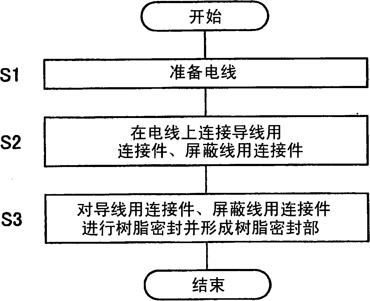
[0120] figure 1 It is a flowchart showing the schematic flow of steps of the wire component manufacturing method for manufacturing the wire component according to Embodiment 1 of the present invention.

[0121] Fu...

Embodiment approach 2

[0236] The electric wire composite printed wiring board according to Embodiment 2 of the present invention (FIG. 19A, FIG. 19B, and FIG. 19C show key parts in the completed state) and the electric wire composite printed wiring circuit for manufacturing the electric wire composite printed wiring board will be described based on FIGS. 12 to 19C. board manufacturing method.

[0237]The electric wire composite printed wiring board of this embodiment is composed of the electric wire component 30 described in Embodiment 1, and therefore it is cited as appropriate and its description is omitted. Furthermore, the features of the electric wire component 30 described in Embodiment 1 are applied as they are.

[0238] Furthermore, the part other than the wire component 30 of the wire combined wire combined printed circuit board is constituted as a rigid part, and an example of a 4-layer wiring structure (the inner layer circuit board with wiring layers on both sides, the inner layer circu...

Embodiment approach 3

[0294] An electronic device (not shown) according to this embodiment is an electronic device on which the cable-built-up printed wiring board according to Embodiment 2 is mounted. That is, an electronic device on which a wire-assembled printed wiring board to which the wire parts 30 are connected is mounted.

[0295] Since the wire-combined printed circuit board can be miniaturized, thinned and freely three-dimensionally arranged according to the shape of the housing, it can be made into an electronic device that can miniaturize and thinn the housing and be in a desired shape and has high reliability.

[0296] Furthermore, as electronic equipment, there are communication terminals such as mobile phones that require excellent high-frequency electrical characteristics and small size and light weight.


PUM


Abstract

The present invention provides a cable-type composite printed wiring board, cable component and electronic device. An embodiment of the present invention is provided with a first wiring board, a cable component juxtaposed with the first wiring board, and second wiring boards laminated onto the first wiring board, which have a second conductor layer pattern connected to the cable component and a second insulating substrate. The cable component comprises a cable having a conductor wire and a sheath portion insulating the conductor wire and a planetary gear-shaped conductor wire coupler connected to the conductor wire and having conductor wire projections which, by passing through the second insulating substrate, abut against the second conductor layer pattern.

Description

[0001] This application claims priority based on Patent Application No. 2007-196334 filed in Japan on July 27, 2007 under Article 119(a) of the Patent Law. By mentioning here, the entire contents of which are incorporated into this application. technical field [0002] The present invention relates to an electric wire composite printed wiring circuit board equipped with electric wire components having connectors butted with the wiring circuit board, electric wire components used for such electric wire composite printed wiring circuit boards, and electronics loaded with such electric wire composite printed wiring circuit boards. equipment. Background technique [0003] In small, light-weight electronic devices that handle high-frequency wireless signals such as mobile phones, in order to promote miniaturization and high-density mounting, the use of wires that perform three-dimensional wiring between printed circuit boards and can cope with electromagnetic shielding and high f...

Claims


Application Information

Patent Timeline
Patent Type & Authority Applications(China)
IPC IPC(8): H05K1/14H05K1/18H01B7/40H01B11/06
CPCH05K3/4652H05K2201/09809H05K3/3405H05K2201/10356H01R4/2404H05K2201/09163H05K1/0243H05K2203/1189H01R9/0515
Inventor 樫尾仁司
Owner SHARP KK
Why Eureka
Try Eureka