Pneumatic air distributing engine

An engine and pneumatic technology, applied in combustion engines, machines/engines, internal combustion piston engines, etc., can solve the problems of easy formation of vibration lines on the cylinder surface, easy overspeed at no-load, and high manufacturing costs

Inactive Publication Date: 2009-02-11
蔡盛龙
View PDF0 Cites 7 Cited by
  • Summary
  • Abstract
  • Description
  • Claims
  • Application Information

AI Technical Summary

Problems solved by technology

[0004] Although the performance of reciprocating piston engines is increasing day by day, the cost has also increased
Moreover, due to the inevitable inertial force limitation produced by the reciprocating mass of the valve transmission mechanism and the piston connecting rod device, its performance will continue to be greatly improved, and there are certain difficulties.
The triangular rotary piston engine has no reciprocating mass and successfully avoids the limitation of inertial force, but it also suffers from the Corio

Method used


Image

  • Pneumatic air distributing engine
  • Pneumatic air distributing engine
  • Pneumatic air distributing engine

Examples


Embodiment Construction

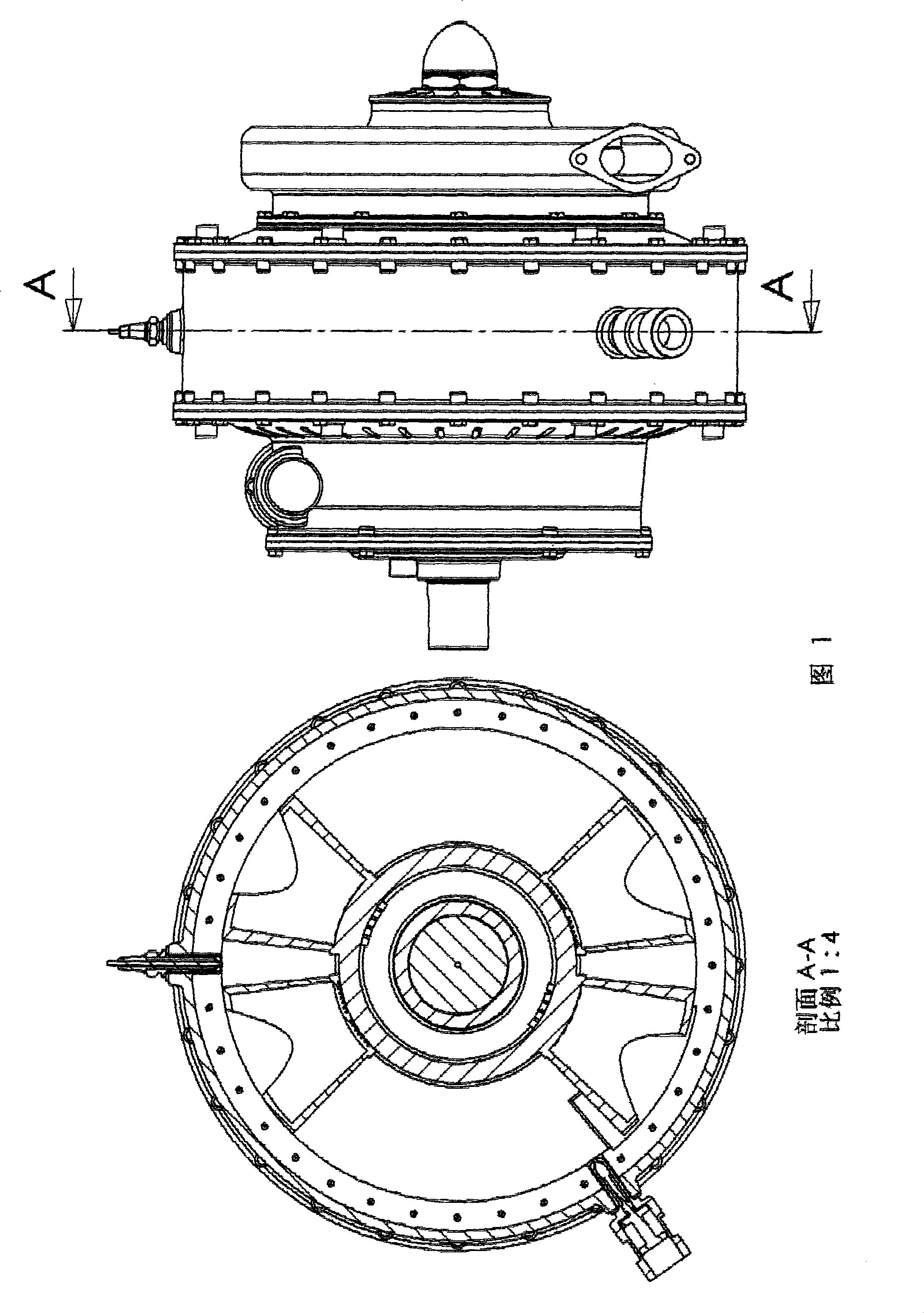
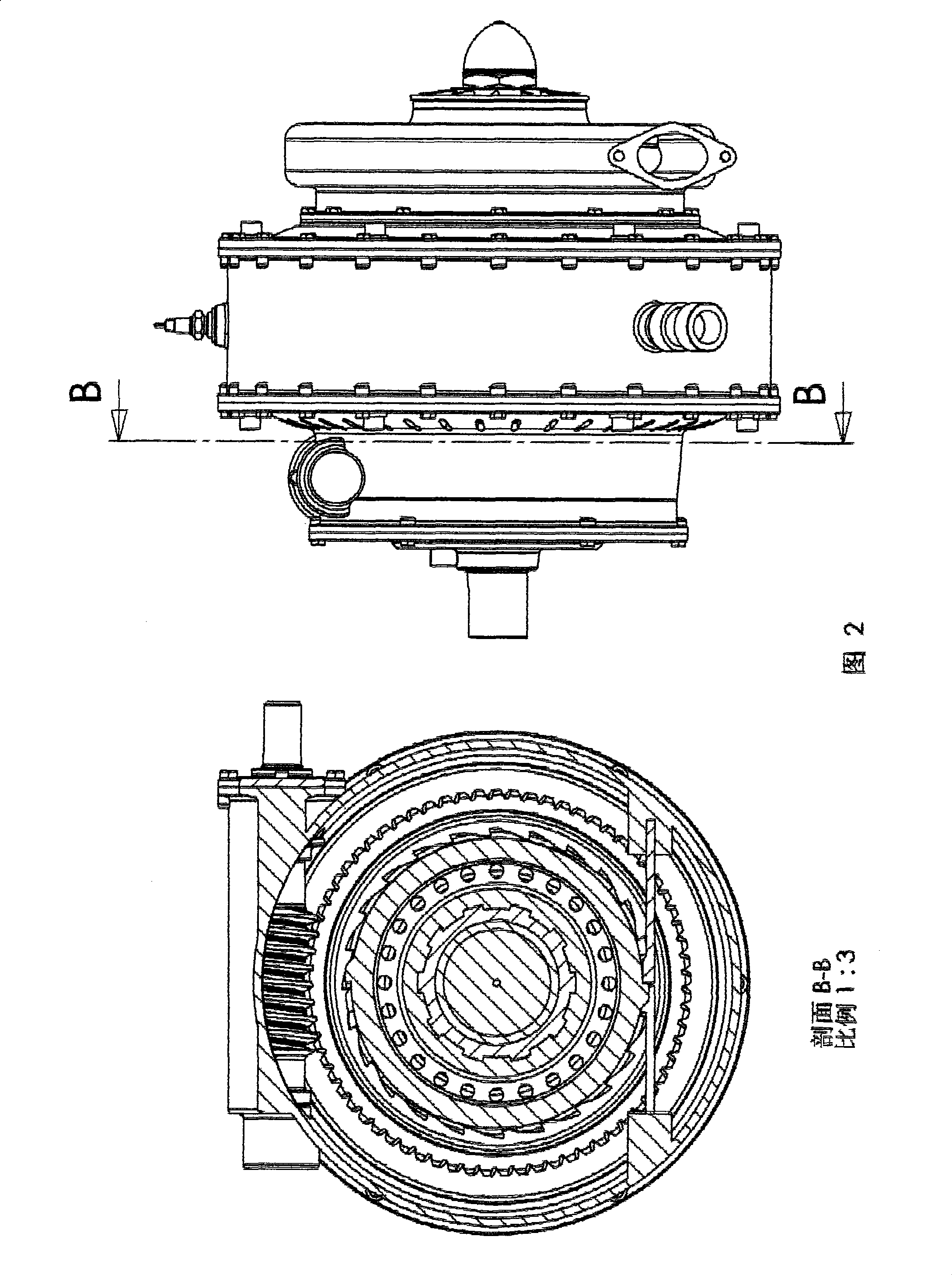
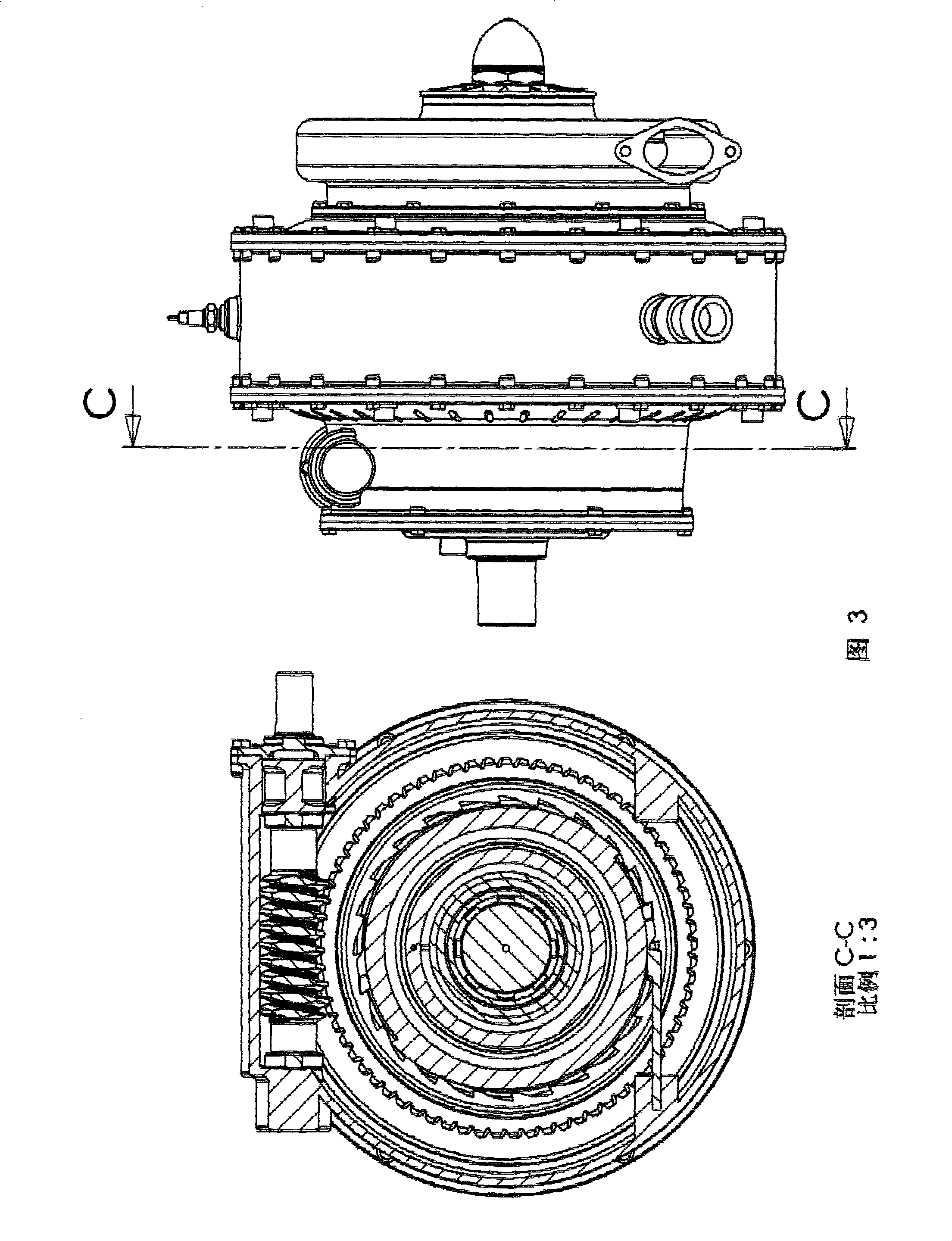
[0065] It can be seen from Figure 2 that the assembly structure of the engine is as follows: the main shaft (1) is engaged with the starting cam (2), the power piston (6) and the centrifugal impeller (9) through splines, and the starting pawl ( 3), the gas distribution spring (5) is installed on the starting cam (2), one end of the gas distribution spring (5) is inserted into the small hole of the spoke plate of the starting cam (2), and the other end is inserted into the non-return ratchet (11) in the small hole of the spoke plate. The power piston (6) is fixed on the main shaft (1) with a nut (7), the centrifugal impeller (9) is fixed on the main shaft (1) with a shaft end nut (10), and the turbine (8) is fixed on the centrifugal impeller (9) with bolts. )superior. Main shaft (1) is supported on end cover (14) and rear casing (21) with bearing (29). The gas distribution piston (13) is supported on the main shaft (1) through sliding bearings, and the non-return ratchet (11)...


PUM


Abstract

The invention relates to a pneumatic air distribution engine which can significantly improve thermal efficiency and reduce pollution emission, production cost as well as maintenance expense. By adopting the novel pneumatic air distribution technology, the pneumatic air distribution engine can drive a piston to do rotation with variable angular velocity or with constant angular velocity by relying on gas pressure and a control mechanism, thus meeting the basic requirements of the Otto cycle in the way of changing the motion property of the key components of the engine. The pneumatic air distribution engine adopts high-temperature resistant structure ceramics as the high-temperature resistant components of the engine, abandons a sealing system and a valve structure of the traditional engine, simplifies a cooling and lubricating system and is simpler in structure and cheaper in price than any traditional engines. By adopting two transduction ways, namely, piston way and turbine way, the pneumatic air distribution engine has extremely high volumetric efficiency, combustion efficiency, mechanical efficiency as well as thermal efficiency when working under the condition of high temperature, high speed and high compression ratio, and shows the characters of the existing shaft power engine such as low fuel consumption, low emission, low production cost and little maintenance. Diagram 1 is the front view (omitted in appendix) of the engine, and A-A is the sectional view thereof.

Description

technical field [0001] This invention relates to internal combustion engines, and more particularly to rotary piston and turbo compound engines. Background technique [0002] The internal combustion engine converts the chemical energy of the fuel into mechanical energy by compressing the working fluid, adding heat to the working fluid, and utilizing the thermal expansion of the working fluid to do work. The compression method of the working medium is different, and the effect on the environment is also different. The turbine uses impeller machinery to realize the compression and work of the working medium, and a large amount of working medium gas is required to participate in the work. The gas after doing work still has a relatively high temperature, and because the mass of the working fluid is very large, the heat energy discharged with the tail gas is also relatively large. The piston machine relies on the volume change of the closed container to realize the compression ...

Claims


Application Information

Patent Timeline
IPC IPC(8): F02B53/00
CPCY02T10/17Y02T10/12
Inventor 蔡盛龙
Owner 蔡盛龙
Why Eureka
Try Eureka