Heatsink and semiconductor device with heatsink

A technology of heat sink and sinking body, which is applied in semiconductor devices, semiconductor/solid-state device parts, electric solid-state devices, etc., and can solve the problems of not describing the specific structure of water leakage at the supply port or discharge port, water leakage, etc.

Inactive Publication Date: 2014-06-25
PANASONIC INDAL DEVICES SUNX
View PDF5 Cites 0 Cited by
  • Summary
  • Abstract
  • Description
  • Claims
  • Application Information

AI Technical Summary

Problems solved by technology

However, since multiple locations must be coupled in a watertight manner, there is a problem that the possibility of water leakage becomes high
In addition, there is no specific structure for preventing water leakage from the supply port or the discharge port, and the prevention of water leakage is considered to be obtained by sandwiching resin or metal pieces between planes

Method used


Image

  • Heatsink and semiconductor device with heatsink
  • Heatsink and semiconductor device with heatsink
  • Heatsink and semiconductor device with heatsink

Examples


no. 1 example

[0048] As an example, the heat sink described below will be explained by taking the case where the heat sink includes a UV-ray light emitting diode as a heat generating element. Incidentally, in the present invention, not only UV-ray light-emitting diodes that emit light in the ultraviolet wavelength range, but also light-emitting diodes other than UV-ray light-emitting diodes, such as light-emitting diodes that emit light in the visible wavelength range, can be used as the heating element . Furthermore, other power semiconductor components can also be used as heating elements.

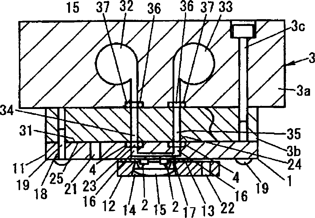
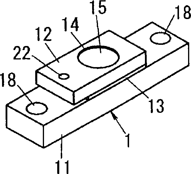
[0049] Such as figure 1 As shown in 3 to 3, the heat sink body 1 is constructed as a layered product produced by laminating a base substrate 11, a cover substrate 12 and an insulating material layer 13. The base substrate 11 is made of a metal plate on which a corresponding carrier chip ( The UV-ray light-emitting diode 2 of bear chip), the cover substrate 12 is made of a metal plate surrounding the...

no. 2 example

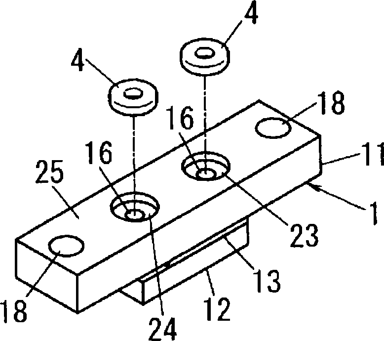
[0065] In the first embodiment, there is provided a structure in which the heat sink body 1 and the head 3 are coupled in a watertight manner by using the seal 4 . On the other hand, in the present embodiment, there is provided a structure employing the sheet seal 5 instead of the ring seal 4 . Furthermore, in the first embodiment, recesses 23 and 24 for accommodating the seal 4 are provided in the heat sink body 1 . On the other hand, in the present embodiment, the recesses 23 and 24 are unnecessary.

[0066]The seal 5 has such a size as the entire area of ​​the surface of the base substrate 11 constituting the heat sink body 1 opposite to the head 3 . The seal 5 is composed of a material exhibiting rubber elasticity, similarly to the seal 4 . In the seal 5, supply holes 41 and discharge holes 42 for connecting the supply port 34 and the discharge port 35 to the respective flow holes 16 are provided so that at positions corresponding to the flow holes 16 in the heat sink bo...

no. 3 example

[0071] In this example, if Figure 9 and 10 As shown in FIG. Body 1. The flow orifice 16 is formed by inserting tubes 26 and 27 .

[0072] In head 3, as in Figure 10 As shown, a first receiving pipe 38 and a second receiving pipe 39 are formed, the first receiving pipe 38 communicates with the supply path 32 at one end, and opens to the supply port 34 at the other end, and the second receiving pipe 39 communicates with the discharge port 39 at one end. The path 33 communicates and opens to the discharge port 35 at the other end. Inside each of the receiving pipes 38 and 39 , a pair of holding grooves 38 a and 39 a are formed to hold the sealing member 7 so as to hold the sealing member 7 at a predetermined position in the receiving pipes 38 and 39 .

[0073] The receiving tubes 38 and 39 have a diameter and a height into which the insertion tubes 26 and 27 can be inserted. The seal 7 is in close contact with the outer circumferential surfaces of the insertion tubes 26 a...


PUM


Abstract

A heatsink carries a UV-ray light emitting diode. Flow passages for causing circulation of a fluid that cools the UV-ray light emitting diode are opened in the heatsink. Supply ports and discharge ports are opened in a mount surface of a header where supply and discharge of the fluid for cooling purpose to and from the heatsink are performed. A pair of circulation orifices corresponding to the supply port and the discharge port are opened in the contact surface that contacts the mount surface in the heatsink. Recesses are formed around the respective circulation orifices, and an annular sealing member that exhibits rubber elasticity and that is compressed between the heatsink and the header is disposed in each of the recesses.

Description

technical field [0001] The present invention relates to a heat sink for cooling a heat generating element, which is a semiconductor element, by using a fluid for cooling, and a semiconductor device having the heat sink. Background technique [0002] Heretofore, heat sinks and heat sinks have been used to cool heat generating elements such as semiconductor elements. In particular, since the heat generation amount of a power semiconductor device is large, a layout for circulating a cooling fluid in a heat sink has been proposed (for example, see JP-A-2006-19676). [0003] JP-A-2006-19676 describes a unit module light source in which a heat sink provided with a light emitting diode serving as a heat generating element is fixed to a fixing jig by screws. Also described is the use of a resin or metal part between the heat sink and the fixing fixture for coupling the supply port and the discharge port to the supply port and the discharge port of the fixing fixture, the supply por...

Claims


Application Information

Patent Timeline
Patent Type & Authority Patents(China)
IPC IPC(8): H01L23/34
CPCH01L2924/0002
Inventor 乾刚司门户秀夫川本吉伸
Owner PANASONIC INDAL DEVICES SUNX
Why Eureka
Try Eureka