Method for polishing circular stainless-steel accurate parts on old machine tool

A technology of precision parts and stainless steel, applied in the field of polishing, can solve problems such as inability to meet requirements, low work efficiency, deformation, etc., and achieve the effect of good polishing effect, easy operation and high polishing efficiency.

Inactive Publication Date: 2009-02-18
江苏星河集团有限公司 +1
View PDF0 Cites 16 Cited by
  • Summary
  • Abstract
  • Description
  • Claims
  • Application Information

AI Technical Summary

Problems solved by technology

There are many common polishing methods. One is to use chemical or electrolytic polishing methods. Due to chemical or electrolytic effects, a certain amount of corrosion is caused to the surface of the polished part. The general corrosion amount is 0.03 to 0.08 mm. The hardness layer is corroded; the second is to adopt mechanical vibration polishing method, because the high-hardness polishing material will grind the sharp edge (acute angle) of the polished part; the third is to use traditional manual polishing, which not only has low work efficiency, but also causes deformed and damaged
None of the above methods can meet the requirements

Method used


Image

  • Method for polishing circular stainless-steel accurate parts on old machine tool
  • Method for polishing circular stainless-steel accurate parts on old machine tool
  • Method for polishing circular stainless-steel accurate parts on old machine tool

Examples


Embodiment 1

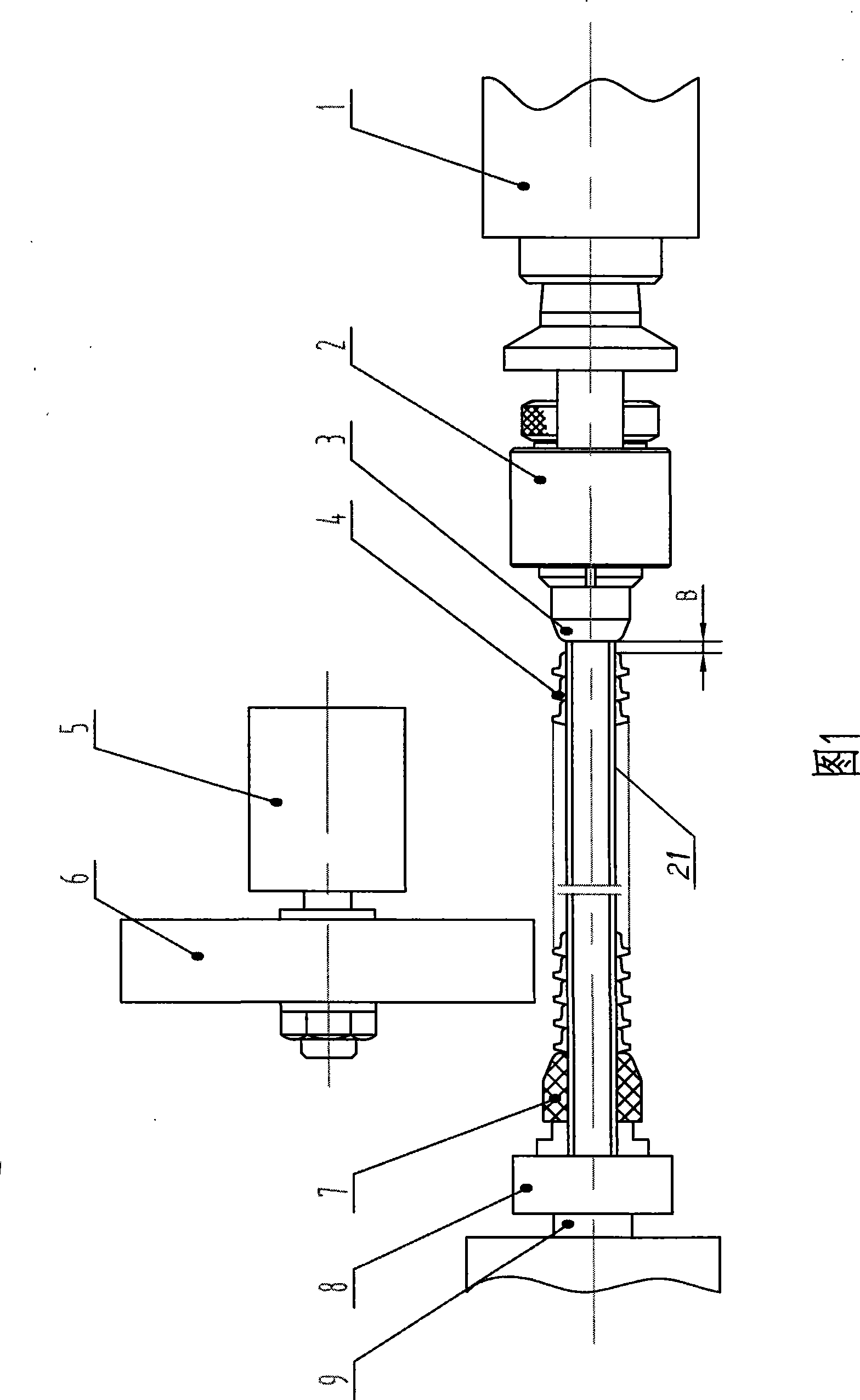
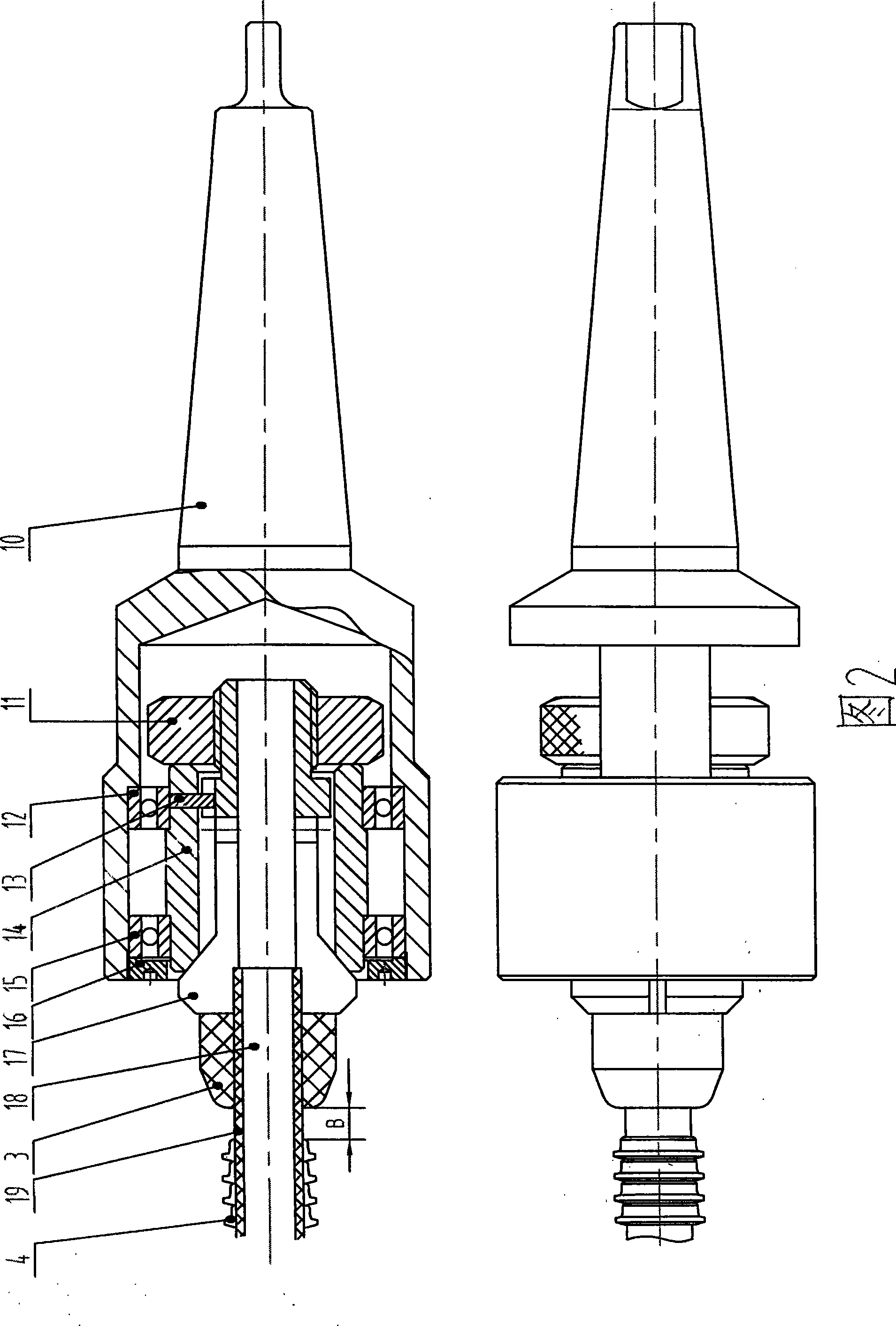
[0018] Degrease the surface of the polished part (4), ultrasonically clean it in an aqueous solution of detergent for about 10 minutes, take it out and dry it. As shown in Figure 1, utilize an old cylindrical grinding machine, install a soft cloth polishing wheel (6) on the grinder (5) of the grinder, adjust the center line of the grinder (5) and the machine tool spindle (9) and The centerlines of the tailstock (1) of the machine tool are kept parallel. Polishing rod (21) as shown in Figure 3, its surface is wiped and coated with polishing wax, and the starting end of cloth tape (19) winding is clamped on the three-jaw chuck (8) of machine tool main shaft (9), makes cloth tape (19) ) and the metal round bar (18), put on the isolation gasket (7) and a certain number of polished parts (4), then put the isolation gasket (3), adjust the polished parts (21) on the polishing rod (21) 4) gap B (gap B=3-10mm adjusted according to the wall thickness and length of the polished part (4)...

Embodiment 2

[0023] The difference with embodiment 1 is: as shown in Figure 1, utilize an old common lathe, the small plank is removed from the middle plank; A soft cloth polishing wheel (6) is installed on the On the main shaft, fix the grinder (5) to the middle carriage, adjust the installation angle and height so that the center line of the grinder (5) is in the center of the longitudinal guide rail of the lathe and the center of the machine tool spindle (9) and the tailstock (1) of the machine tool The lines are kept parallel, and the deviation between the height of its center and the center of the main shaft is not more than 30 mm. Start the grinder (5) and the main shaft of the machine tool, so that the soft cloth polishing wheel (6), the main shaft of the machine tool (9) and the three-jaw chuck (8) drive the polishing rod (21) that a certain number of polished parts (4) are housed At the same time, rotate clockwise to adjust the force of the soft cloth polishing wheel (6) on the po...

Embodiment 3

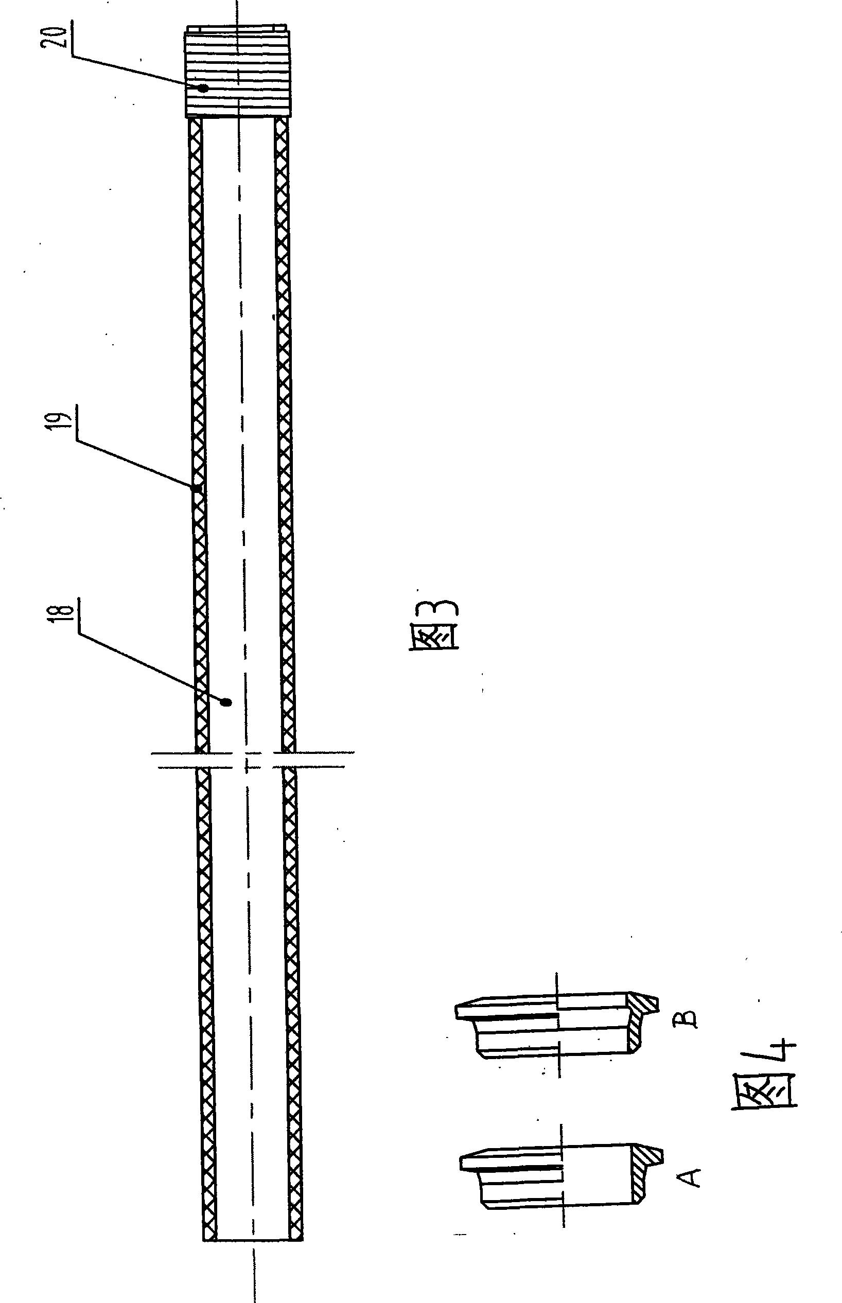
[0025]The difference with embodiment 1 is that if the inner hole of the polished part (4) has a groove-shaped structure, as shown in B in Figure 4, in order to make the inner hole groove, it can be polished to the same effect as other positions The cloth tape (19) wound on the polishing rod (21) should adopt a thicker material, such as woolen or wool-linen blended cloth, etc., due to a certain thickness, the wound polishing rod (21) is more plump and smooth It is elastic and more conducive to polishing the inner groove of the inner hole. Use a metal round rod (18) with a diameter less than 3 to 5 mm in diameter of the polished part (4) and a length of 25 to 35 times the inner diameter of the polished part (4), and a cloth tape (19) from the metal round rod One end of (18) is spirally wound evenly and evenly in a clockwise direction to the other end. The cloth tape (19) and the metal round rod (18) are clamped by the three-jaw chuck (8) at the starting end, and the other end is...


PUM


Abstract

The invention provides a method for polishing an annular stainless steel precise part in an old machine tool, which is applied to the mechanical manufacturing industry. On the premise of not influencing the precision of the dimension of the prior part, the method can ensure that the surface of the part achieves higher luminance brightness and keeps a necessary acute angle. The method is characterized in that a specially-made polishing rod is used; one end of the polishing rod is clamped on a three-claw chuck of a mainshaft of an old cylindrical grinding machine or a common lathe; after spacer rings and a plurality of polished parts are sleeved on the polishing rod, and limit sleeves are mounted; a loose clamp arranged on a tail rack of the machine tool tightly clamps the other end of the polishing rod; a soft cloth polishing wheel is arranged on a grinding wheel machine and is positioned between the three-claw chuck and the loose clamp; after the startup, the soft cloth polishing wheel and the polishing rod clamped on the three-claw chuck rotate along clockwise direction; and the position of the soft cloth polishing wheel rotating at high-speed and the acting force between the soft cloth polishing wheel and the polished part are adjusted so as to implement the inner, the outer and the bilateral soft polishing to the polished part between the three-claw chuck and the loose clamp, thereby achieving the aim of polishing.

Description

Technical field: [0001] The invention relates to a polishing technology in mechanical processing, in particular to a process method for surface polishing of a small circular stainless steel precision part, which achieves a bright surface and maintains a necessary acute angle without affecting the dimensional accuracy of the part. Background technique: [0002] In order to improve the performance or appearance quality of the products, many precision parts of small circular stainless steel need to be polished to obtain higher surface roughness and brightness without affecting the dimensional accuracy of the original parts. For example, the rear ferrule, an important part of the stainless steel double ferrule pipe joint, is a typical case. It needs to obtain a surface hardness layer through heat treatment (the thickness of the hard layer is only 0.025-0.05mm). Excellent surface roughness and brightness, but also maintain a sharper edge (acute angle). Polishing is required due ...

Claims


Application Information

Patent Timeline
Patent Type & Authority Applications(China)
IPC IPC(8): B24B29/04
Inventor 朱义芳
Owner 江苏星河集团有限公司
Why Eureka
Try Eureka