Unit bypass apparatus and control method of unit cascading high voltage frequency convertor

A high-voltage inverter, bypass device technology, applied in emergency protection circuit devices, output power conversion devices, electrical components, etc., can solve the problems of reduced system reliability, short-circuit failure of power units, burnout, etc., to improve safety. performance and reliability, improve the withstand voltage level, and avoid the effect of misleading

Inactive Publication Date: 2009-02-18
HUBEI SANHUAN DEV
View PDF0 Cites 12 Cited by
  • Summary
  • Abstract
  • Description
  • Claims
  • Application Information

AI Technical Summary

Problems solved by technology

When a unit fails, the drive pulse of the inverter bridge is blocked, and the thyristor is triggered at the same time, so that the phase current of the phase where the unit is located flows through the bypass formed by the diode rectifier bridge and the thyristor. At this time, the faulty unit is cut off by the bypass, and the bypass The structure of the bypass device is simple, small in size, light in weight, and easy to maintain. However, there are the following problems: 1. When the control pulse of the unit power switching device IGBT is blocked or the output voltage of the power unit is at zero level, the voltage across the thyristor in the bypass device At this time, if the IGBT is controlled so that the output of the power unit has a level, the DC voltage of

Method used


Image

  • Unit bypass apparatus and control method of unit cascading high voltage frequency convertor
  • Unit bypass apparatus and control method of unit cascading high voltage frequency convertor
  • Unit bypass apparatus and control method of unit cascading high voltage frequency convertor

Examples


Example Embodiment

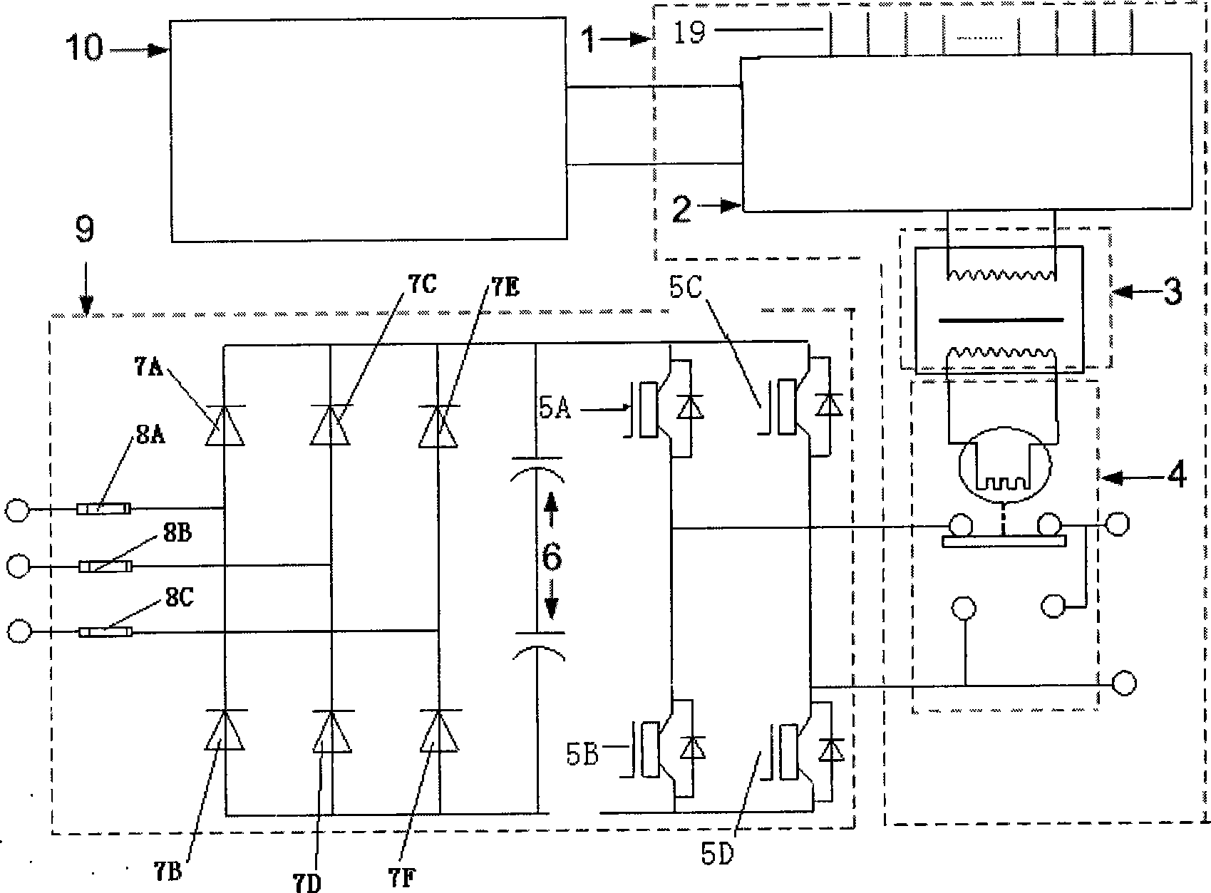
[0020] like figure 1 As shown, the power unit 9 is mainly composed of fuses 8A, 8B, 8C, rectifier diodes 7A, 7B, 7C, 7D, 7E, 7F, filter capacitor 6, and power switching devices 5A, 5B, 5C, 5D. Six rectifier diodes form a three-phase full-wave rectifier bridge, and the three-phase AC power supply is connected to the input end of the rectifier bridge through a fuse. The output end of the rectifier bridge is connected in parallel with the capacitor bank formed by the filter capacitor 6 . Four power switching devices (such as IGBTs) form an H-shaped inverter bridge. The input end of the inverter bridge is connected to the capacitor bank formed by the filter capacitor 6 , and the output end is connected to the bypass contactor 4 . The power unit 9 is the basic unit of the series-connected high-voltage frequency converter, its structure has been widely adopted at the present stage, and its technology is quite mature.

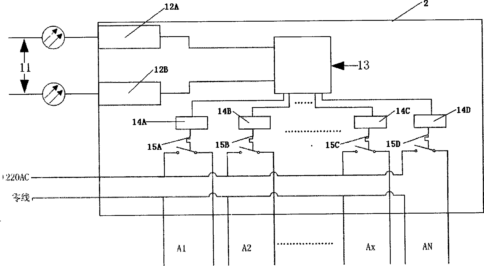
[0021] The bypass device 1 of the present invention is compose...


PUM


Abstract

The invention discloses a unit by-path apparatus for a unit cascade high voltage frequency converter, and control method thereof, wherein a by-path centralized control board being connected with a main circuit control board and an isolation transformer separately; the other end of the isolation transformer being connected with a by-pass contactor which is connected with an unit output. The by-pass apparatus is composed of a main circuit control board, a by-path centralized control board, an isolation transformer, and a by-path contactor. The method includes the steps of transferring a unit fault signal to the main circuit control board firstly; cutting off the main circuit current; thirdly, the by-path centralized control board transmitting a by-path contactor motion completion signal to the main circuit control board; fourthly, the main circuit control board transmitting IGBT control signal based on the acquisition motor backemf. The apparatus of the invention has a simple structure, and can cut off the failure unit by path completely reliably, eliminate the error and refused onstate of other type by-pass systems, and assure the safe and reliable motion of the whole by-pass method.

Description

technical field [0001] The invention belongs to the technical field of power electronics. More specifically, it is a unit bypass device of a unit series high-voltage frequency converter, which is suitable for any similar unit series device, and also relates to a control method for the bypass device. Background technique [0002] With the wide application of high-voltage frequency converters in important occasions such as electric power, metallurgy, petroleum, and chemical industry, higher requirements are put forward for the stable and reliable operation of high-voltage frequency converters. At present, the main circuit of high-voltage inverters generally adopts the power unit series technology, which has the advantages of small harmonics, interchangeable units, mass production, and convenient maintenance. However, failure of one or several power units during operation will cause the entire The frequency converter cannot operate normally, or even trips, which greatly reduce...

Claims


Application Information

Patent Timeline
IPC IPC(8): H02M5/44H02M5/458H02M1/32H02H7/122
Inventor 王宏英毕平劲查晓明
Owner HUBEI SANHUAN DEV
Why Eureka
Try Eureka