Coherent light receiving system

A coherent optical and receiver technology, applied in the field of optical communication systems, can solve the problems of inability to achieve 40Gbps fast signal light and inability to receive, and achieve the effects of reduced size and simplified structure

Inactive Publication Date: 2009-02-18
FUJITSU LTD
View PDF2 Cites 43 Cited by
  • Summary
  • Abstract
  • Description
  • Claims
  • Application Information

AI Technical Summary

Problems solved by technology

[0003] However, a coherent optical receiving system has a fundamental problem that reception cannot be performed when the polarization state of the local oscillator light output from the local oscillator light source provided for the optical receiver is orthogonal to the polarization state of the received signal light
[0019] Therefore, the conventional coherent optical receiver in the system (III) needs a circuit whose bandwidth is three times or more (that is, 120Gbps or more) of the signal bandwidth of the signal light of 40Gbps, and cannot realize the fast signal light of 40Gbps or more.

Method used


Image

  • Coherent light receiving system
  • Coherent light receiving system
  • Coherent light receiving system

Examples


no. 1 approach

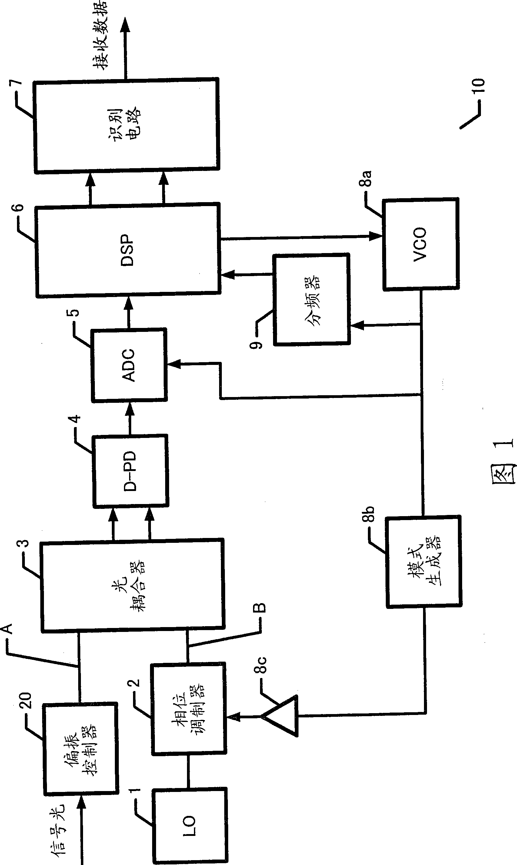
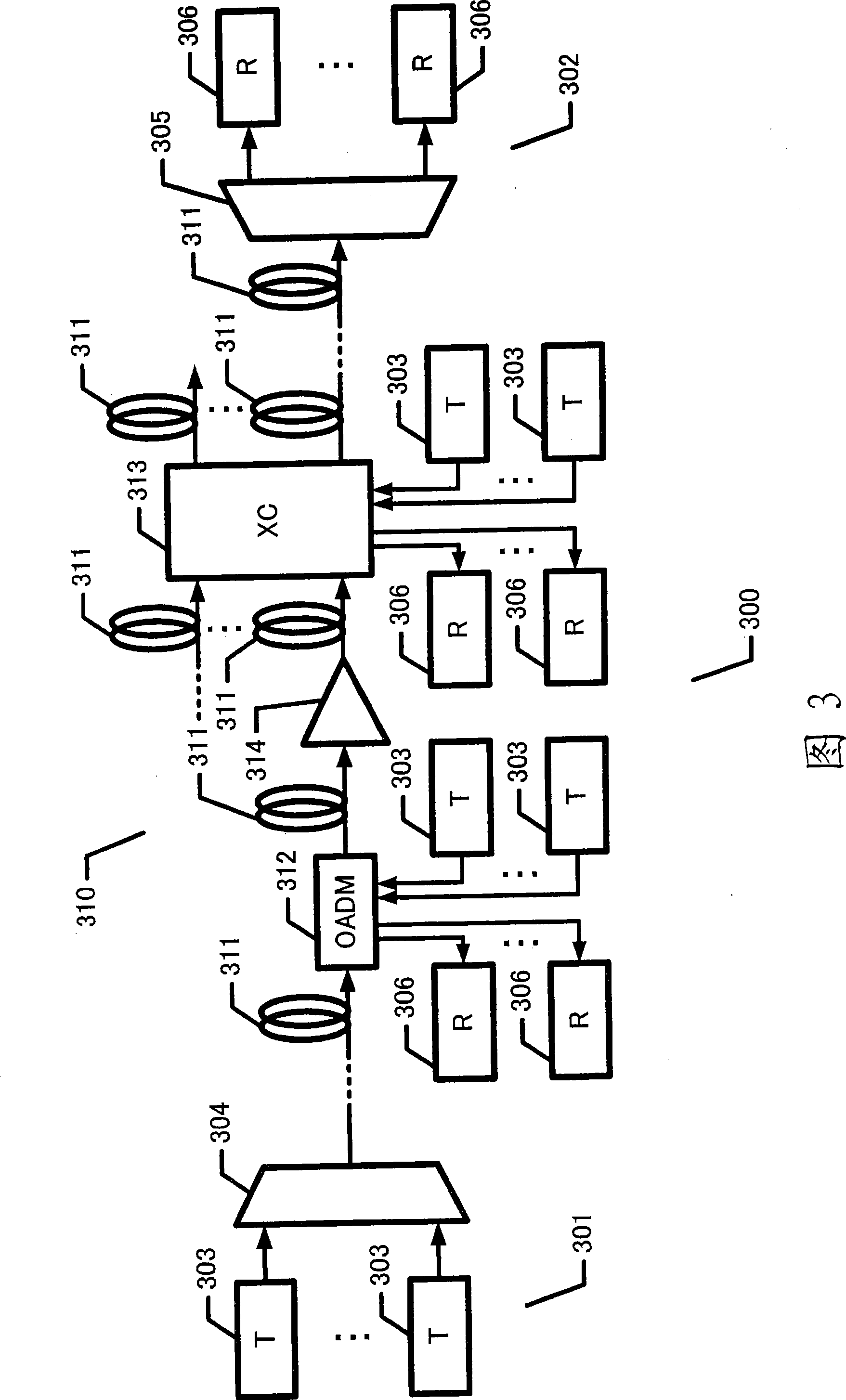
[0045] Fig. 1 shows a coherent optical receiver 10 according to a first embodiment. The coherent optical receiver 10 shown in FIG. 1 can be applied as the optical receiver 306 in the optical communication system 300 shown in FIG. 3 . Here, in the optical communication system 300 shown in FIG. 3 , the WDM transmitting device 301 is connected to the WDM receiving device 302 via the optical network 310 .

[0046] The wavelength division multiplexing transmission device 301 includes: a plurality of optical transmitters (T) 303 outputting optical signals having different wavelengths; and a wavelength multiplexer 304 . The optical transmitter 303 modulates light using multi-valued phase modulation such as DQPSK, QPSK, and QAM (Quadrature Amplitude Modulation), and outputs the modulated light as an optical signal. The wavelength multiplexer 304 multiplexes the optical signal from the optical transmitter 303 in the wavelength domain, and transmits the multiplexed light to the optical...

no. 2 approach

[0090] FIG. 6 is a block diagram showing a coherent optical receiver 10A according to a second embodiment of the present invention. The coherent optical receiver 10A shown in FIG. 6 can be applied as the receiver 306 shown in FIG. 3 and includes a modulated local light generator different from the coherent optical receiver (see reference numeral 200) shown in FIG. 15 11.

[0091] Referring to FIG. 6, a coherent optical receiver 10A includes: an identification circuit 7; a VCO 8a; and a frequency divider 9, which are basically the same as those according to the first embodiment. In addition, the coherent optical receiver 10A also includes: a modulated local light generator (LL GEN) 11; a 2×4 phase mixing circuit 12 as an optical mixer; a differential photodetector (D-PD) 13- 1 and 13-2; ADCs 14-1 and 14-2; digital signal processor 15; and repeating pattern generator 8e.

[0092] The modulated local light generator 11 outputs the local oscillator light for coherent light recep...

no. 3 approach

[0193] FIG. 12 is a block diagram showing a coherent optical receiver 10B according to a third embodiment of the present invention. The coherent optical receiver 10B shown in FIG. 12 can be used as the optical receiver 306 in FIG. 3 . Here, the coherent optical receiver 10B according to the third embodiment includes a polarization modulator (POL-MOD) 11A (see reference numeral 11 in FIG. 7 , 10 or 11 according to the second embodiment) for polarization modulation instead of The polarization controller 20 in the structure of the coherent optical receiver 10 according to the first embodiment.

[0194] Here, the coherent optical receiver 10B shown in FIG. 12, the LO1, and the phase modulator 2 form a first modulated light output unit for outputting light modulated with an optical frequency based on a second clock phase-synchronized with the first clock. light (local oscillator modulated light). By setting the received signal light as m-value modulated light (mPSK, mQAM, etc.) w...


PUM


Abstract

The invention provides a coherent light receiving system. In order to reduce the size and simplify the structure of a coherent light receiver, the coherent light receiver includes an optical mixer for coupling local oscillator light and reception signal light, a photoelectric converter for photoelectrically converting light coupled in the optical mixer, a reception data processing unit for extracting reception data included in the reception signal light through digital signal processing for processing the coupled signal converted into an electrical signal by the photoelectric converter, based on a first clock, and a modulator for modulating the local oscillator light or the reception signal light inputted to the optical mixer respectively, by using a clock phase-synchronized with the first clock used for the digital signal processing in the reception data processing unit.

Description

technical field [0001] The invention relates to an optical receiver used in an optical transmission system, in particular to an optical receiver of a coherent optical receiving system independent of the polarization state of signal light and an optical communication system. Background technique [0002] In order to realize ultra-fast optical transmission systems of 40Gbps or more, optical receiver-transmitters based on multi-valued phase modulation such as RZ-DQPSK (Return to Zero Differential Quadrature Phase Shift Keying) have been developed. There is a need to further improve the optical noise tolerance of optical receiver-transmitters based on multivalued phase modulation, and to reduce the optical receiver-transmitter the size of. As a means of realizing it, coherent light receiving systems preferably include, for example, homodyne (homodyne) systems, intradyne (intradyne) systems, and heterodyne (heterodyne) systems, and their applications have been studied (for examp...

Claims


Application Information

Patent Timeline
Patent Type & Authority Applications(China)
IPC IPC(8): H04B10/148H04B10/516H04B10/275H04B10/291H04B10/40H04B10/50H04B10/532H04B10/54H04B10/556H04B10/58H04B10/60H04B10/61H04J14/00H04J14/02
CPCH04B10/614H04B10/6151H04B10/6165H04B10/60H04B10/61H04B10/611H04B10/65
Inventor 星田刚司
Owner FUJITSU LTD
Why Eureka
Try Eureka