

Cleaning device using water-based cleaning liquid
A cleaning device and water-based technology, applied in liquid cleaning methods, cleaning heat transfer devices, cleaning methods using gas flow, etc., can solve the difficulty of exhaust devices, large heat loss, and the inability to prevent heat loss and other problems, to achieve the effect of reducing temperature fluctuation and easy temperature adjustment
- Summary
- Abstract
- Description
- Claims
- Application Information
AI Technical Summary
Problems solved by technology
Method used
Image

Examples
Embodiment 1
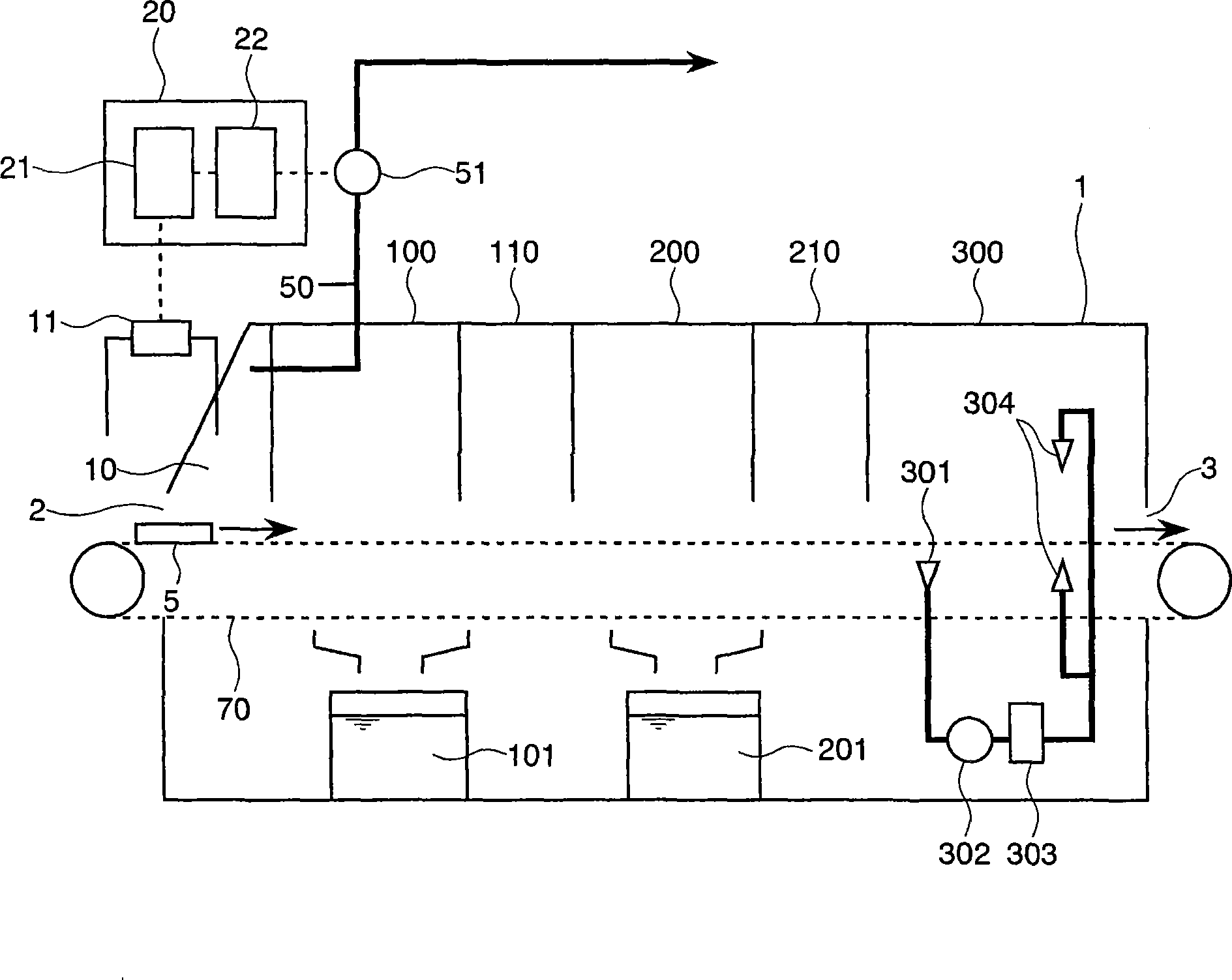
[0161] figure 1 is a schematic configuration diagram of a cleaning device according to a first embodiment of the present invention, figure 2 It is a detailed diagram of the cleaning room and the water removal room.
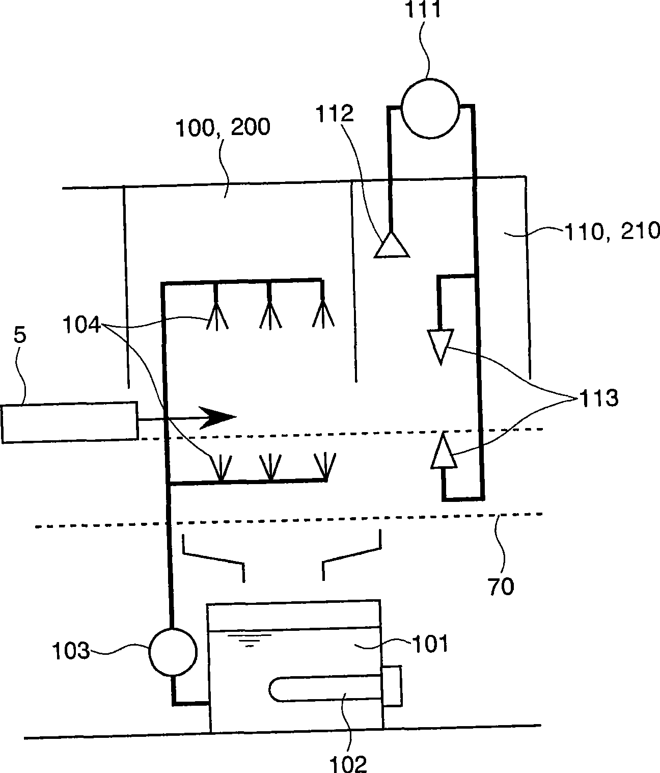
[0162] The cleaning device 1 of the first embodiment is a mesh conveyor conveying device, and is configured to perform the steps of washing, draining, and drying while moving the object 5 to be cleaned using the conveying mesh 70 . According to the conveying order of the objects to be cleaned 5, between the inlet 2 and the outlet 3, there are arranged in sequence: an exhaust chamber 10, a first cleaning chamber 100, a first dewatering chamber 110, a second cleaning chamber 200, and a second dewatering chamber. Water chamber 210, drying chamber 300. In addition, this structure is an example, and the number and order of a washing chamber, a dehydration chamber, and a drying chamber may differ from this.
[0163]A differential pressure gauge 11 is provided on the...
Embodiment 2
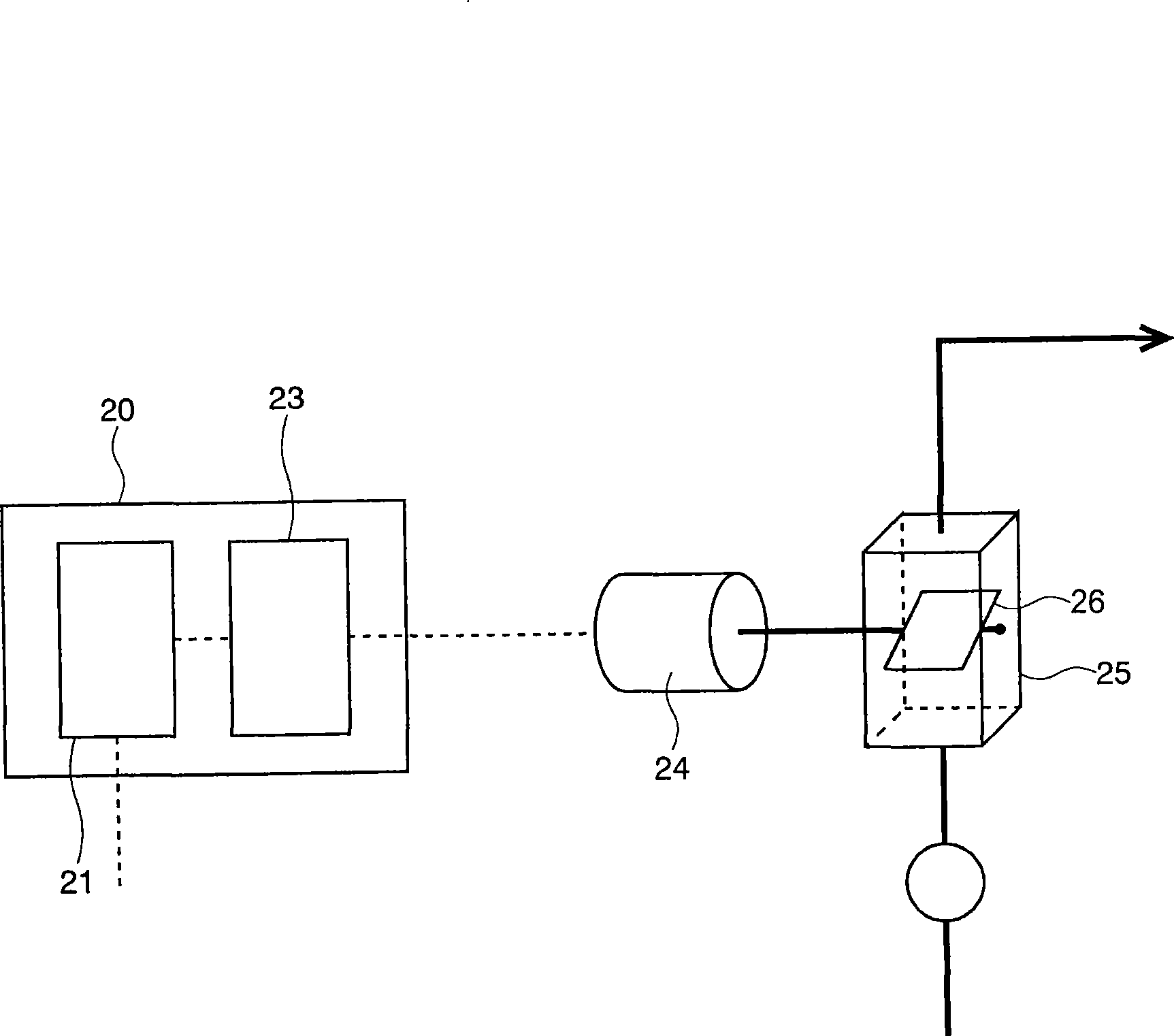
[0173] image 3 It is a schematic configuration diagram showing another method of controlling the exhaust air volume of the exhaust device according to the second embodiment of the present invention.
[0174] The differential pressure data measured by the differential pressure gauge 11 is processed by the arithmetic unit 21 of the control unit 20 as in the first embodiment. In this embodiment, in order to control the exhaust air volume, an air volume adjustment damper mechanism 25 is provided on the blowing side of the exhaust device, that is, the exhaust fan 51 . The opening angle of the baffle plate 26 inside the air volume adjustment baffle plate mechanism 25 is regulated with a servo motor 24 having an angle adjustment function. The operation of the servo motor 24 , that is, the opening angle of the shutter 26 is controlled by the servo control unit 23 in accordance with instructions from the computing device 21 . By adjusting the opening angle of the baffle 26 so that t...
Embodiment 3
[0176] Figure 4 is a schematic configuration diagram of another cleaning device according to the third embodiment of the present invention.
[0177] The cleaning device 4 of Embodiment 3 is an immersion ultrasonic type, which transports the object 5 to be cleaned by the front and rear conveying mechanism 71 and the up and down conveying mechanism 72, and performs cleaning and dewatering processes. A first cleaning chamber 100 , a second cleaning chamber 200 , and a dewatering chamber 110 are sequentially arranged between the inlet 2 and the outlet 3 of the objects to be cleaned. Heaters 102 , 202 and ultrasonic generators 105 , 205 are provided in the water-based cleaning liquid tanks 101 , 201 of the first cleaning chamber 100 and the second cleaning chamber 200 . The object 5 to be cleaned is first immersed in the cleaning solution tank 101 by the vertical conveying mechanism 72 in the first cleaning chamber 100 , and ultrasonically cleaned in the cleaning solution heated ...
PUM
 Abstract
Description
Claims
Application Information