Internal combustion heating moving-bed type biomass pyrolysis liquefying apparatus

A biomass pyrolysis and liquefaction device technology, applied in the field of pyrolysis liquefaction devices, can solve the problems of limited heat, unavoidable shortcomings of reactors and methods, etc., and achieve the goal of improving utilization rate, reducing residence time, and increasing the calorific value of bio-oil Effect

Inactive Publication Date: 2011-09-21
HEFEI UNIV OF TECH
View PDF0 Cites 0 Cited by
  • Summary
  • Abstract
  • Description
  • Claims
  • Application Information

AI Technical Summary

Problems solved by technology

This method can avoid the impact of flue gas on pyrolysis products, but the heat transfer for biomass pyrolysis is limited
[0008] Therefore, when the above three pyrolysis liquefaction reactors use the above four methods to realize the self-heating pyrolysis liquefaction process, the shortcomings of the reactor and the method itself are unavoidable.

Method used


Image

  • Internal combustion heating moving-bed type biomass pyrolysis liquefying apparatus
  • Internal combustion heating moving-bed type biomass pyrolysis liquefying apparatus

Examples


Embodiment Construction

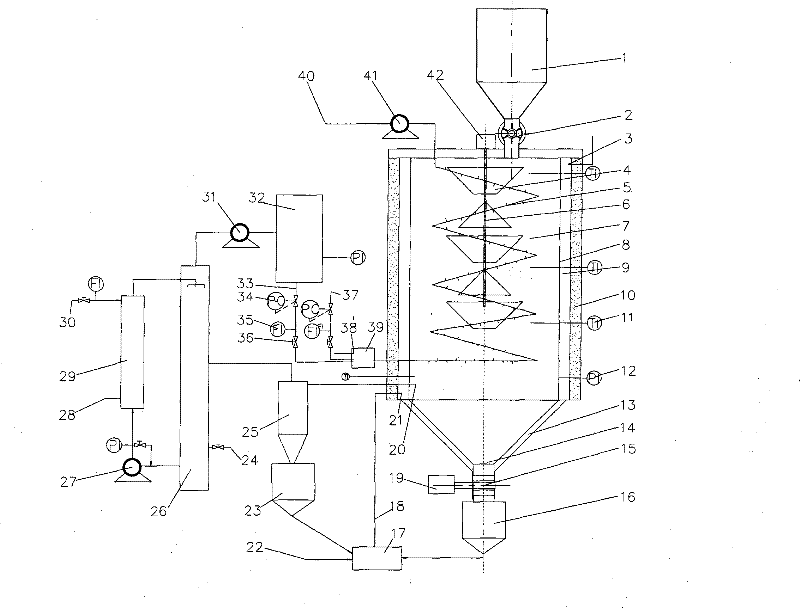
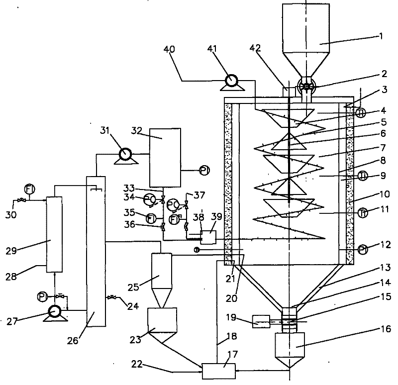
[0032] see figure 1 , the present embodiment adopts the cylindrical reactor 7, and in the inside of the cylindrical reactor 7, a serpentine internal combustion pipeline 5 is arranged, and the entrance of the serpentine internal combustion pipeline 5 is positioned at the bottom of the cylindrical reactor 7, and its outlet is from the cylinder. The top of the tubular reactor 7 extends to the outside of the reactor;

[0033] On the top of the cylindrical reactor 7, a blanking control valve 2 is set, and the feeding port is located at the top eccentric position of the cylindrical reactor 7, and on the central axis of the cylindrical reactor 7, a cone with a cone is set. The rotating shaft 6 of the funnel 4, and there is a conical distributing umbrella between the conical funnels 4, so that the biomass flowing out from the previous conical funnel 4 flows to the next conical funnel after being dispersed by the conical distributing umbrella 4, the residence time of biomass in the re...


PUM


Abstract

The invention discloses an internal combustion heating movable-bed biomass-pyrolysis liquefaction device which includes a reactor (7); the inside of the reactor is provided with an internal combustion pipeline (5); both the inlet and the outlet of the internal combustion pipeline (5) are arranged outside the reactor (7); a hopper (1) is arranged above the reactor (7); a blanking control valve (2)is arranged on the hopper (1); a rotary shaft (6) is arranged in the center of the reactor (7); conical hoppers (4) are arranged on the rotary shaft (6); conical material dividing umbrellas are arranged between the conical hoppers (4); the material inlet of the hopper (1) is arranged above the conical hoppers (4); a pyrolysis gas outlet (20) is arranged on the reactor (7); the bottom part of the reactor (7) is provided with a slag discharge opening (14); a cyclone separator (23) is connected on the gas pipeline of the pyrolysis gas outlet (20); the flue gas outlet of the cyclone separator (23) is connected into a condenser (26); an oil outlet and an outlet for non-condensable gas are arranged on the condenser (26); the outlet for non-condensable gas is connected to a gas buffer tank (28) through a draught fan. The biomass-pyrolysis liquefaction device reduces the liquefaction cost of bio-oil, has a simple structure and a low processing and manufacture cost as well as is simply and conveniently operated, managed and maintained.

Description

technical field [0001] The invention relates to a pyrolysis liquefaction device, more specifically a pyrolysis liquefaction device using biomass as raw material. Background technique [0002] Biomass is a kind of renewable energy with abundant reserves, which can be used as an alternative energy source to achieve CO 2 Zero emission, and the low content of S and N in it can greatly reduce the greenhouse effect and environmental pollution. [0003] At present, the design and research focus of biomass pyrolysis liquefaction equipment is how to better achieve efficient heat transfer and self-heating pyrolysis liquefaction of biomass particles. [0004] For now, the pyrolysis technology based on bubbling fluidized bed, circulating fluidized bed and rotating cone reactor is relatively successful. achieves efficient heat transfer, but works on a completely different principle. [0005] In the fluidized bed reactor, the biomass particles and the heat carrier mainly rely on the dr...

Claims


Application Information

Patent Timeline
Patent Type & Authority Patents(China)
IPC IPC(8): C10B53/02C10G1/00
CPCY02E50/14Y02E50/10
Inventor 陈天虎胡孔元石莹
Owner HEFEI UNIV OF TECH
Why Eureka
Try Eureka