Defoaming method and device for eliminating foam of drilling fluid by thermal radiation

A defoaming device and thermal radiation technology, which is applied in earthwork drilling, wellbore flushing, wellbore/well components, etc., can solve the problems of low mechanical impact efficiency and inapplicability, and achieve energy saving and adjustable heat radiation intensity Effect

Inactive Publication Date: 2009-03-11
SHANDONG UNIV
View PDF2 Cites 15 Cited by
  • Summary
  • Abstract
  • Description
  • Claims
  • Application Information

AI Technical Summary

Problems solved by technology

In the existing physical defoaming process, mechanical impact method is usually used to destroy the foam liquid film so as to achieve the purpose of defoaming, such as the mechanical defoaming device used in patent 200620095219.5 flying saucer centrifugal defoamer, 200320107436.8 papermaking black liquor storage tank defoaming device, However, the efficiency of mechanical impact is low, so it is not suitable for foam drilling where the foam flow is large

Method used


Image

  • Defoaming method and device for eliminating foam of drilling fluid by thermal radiation

Examples


Embodiment 1

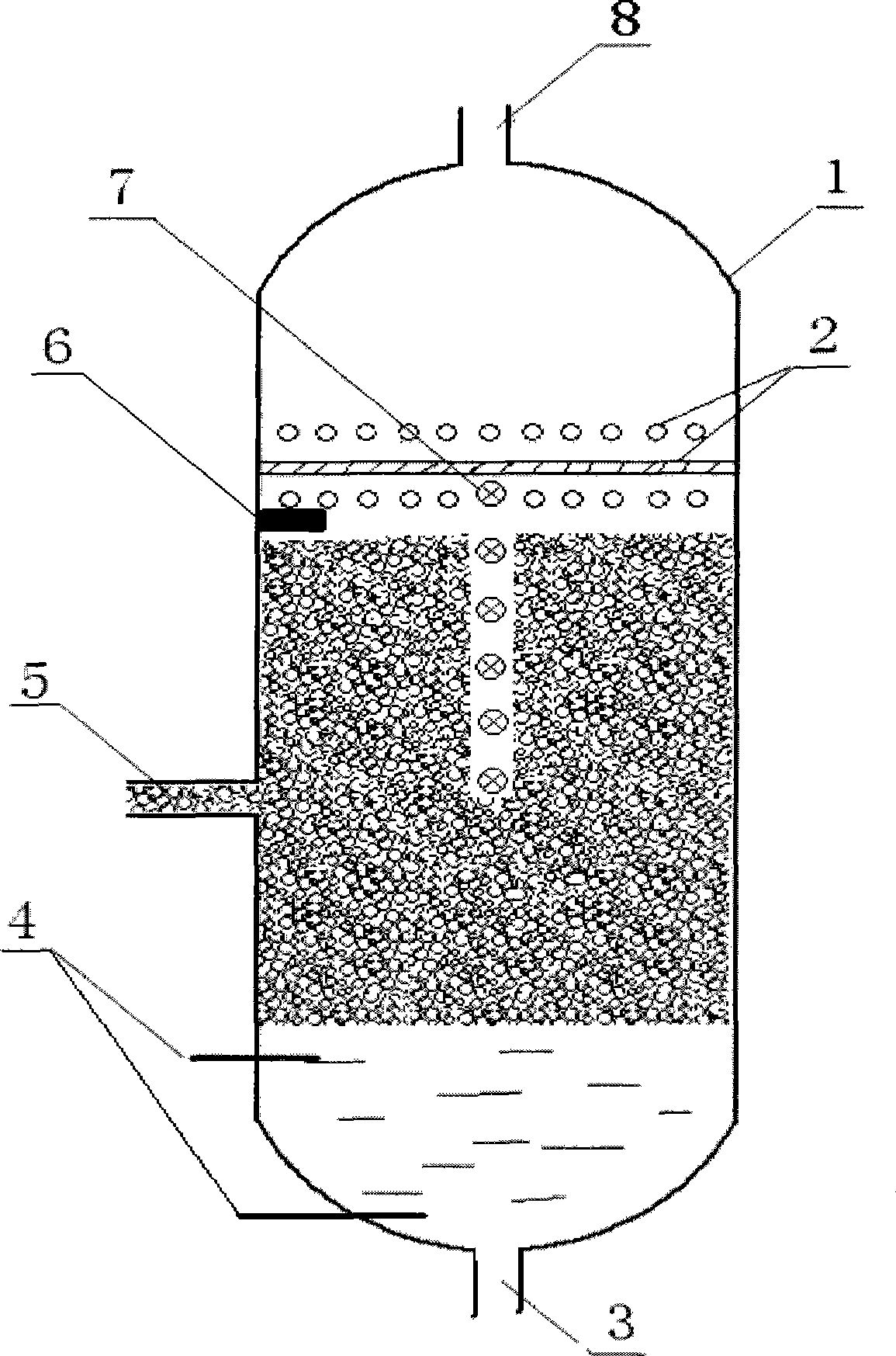
[0033] A defoaming device for eliminating foam in drilling fluid by using heat radiation, comprising a cylindrical container 1, characterized in that the top of the cylindrical container 1 is equipped with a gas outlet 8, the bottom is equipped with a liquid and slag discharge port 3, and the side of the middle and lower part is equipped with There is a foam inlet 5, the upper inner wall is provided with a heat radiation part 2, an ultrasonic foam height sensor 6 is provided below the heat radiation part 2 on the cylindrical container 1, and a temperature sensor 7 is provided under the heat radiation part 2 on the cylindrical container 1 , The middle and lower parts of the cylindrical container 1 are provided with a liquid level sensor 4 .

[0034] The heat radiation part 2 is composed of carbon fiber quartz glass tube.

[0035] The heat radiation component 2 is of an adjustable power type.

[0036] The heat radiation component 2 is in the shape of a fence.

[0037] The heat...

Embodiment 2

[0043] Same as embodiment 1, except that the heat radiation component 2 is composed of electrothermal ceramic tubes.

[0044] The heat radiation component 2 is in the shape of a grid.

[0045] The heat radiation component 2 is divided into multiple layers.

[0046] The temperature sensors 7 are distributed in groups on the cylindrical container 1 in a vertical direction with an interval of 20 cm, the top is below the heat radiation member 2, and the bottom is flush with the foam inlet 5 horizontal line.

[0047] The ratio of the inner diameter of the cylindrical container 1 to the inner diameter of the foam inlet tube 5 is 15:1.

Embodiment 3

[0049] Same as embodiment 1, except that the heat radiation component 2 is composed of electric heating wires.

[0050] The heat radiation component 2 is in the shape of a ring.

[0051] The temperature sensors 6 are distributed in groups on the cylindrical container 1 in a vertical direction with an interval of 15 cm, the uppermost part is below the heat radiation part 2, and the lowermost part is flush with the foam inlet 5 horizontal line.

[0052] The ratio of the inner diameter of the cylindrical container 1 to the inner diameter of the foam inlet 5 tube is 20:1.


PUM


Abstract

The invention relates to a defoaming method and a deforming device for removing the foam of drilling fluid through thermal radiation, which belong to the technical field of the physical defoaming of the drilling fluid. The defoaming device comprises a cylindrical container. The defoaming device is characterized in that a gas outlet is arranged on the top of the cylindrical container, a fluid and slag outlet is arranged on the bottom of the cylindrical container, a foam inlet is arranged on the side face of the middle lower part of the cylindrical container, a thermal radiation element is arranged on the upper inner wall of the cylindrical container, a temperature sensor is arranged below the thermal radiation element on the cylindrical container, an ultrasonic foam height sensor is also arranged below the thermal radiation element on the cylindrical container, and fluid level sensors are arranged on the middle and lower parts of the inside cylindrical container. The foam flows into the device through the foam inlet, the thermal radiation element on the device gives off thermal radiation to break the foam with low intensity near the device, the separated gas is discharged through the gas outlet, and the foam base fluid and the solid carried by the foam are discharged through the fluid and slag outlet. The defoaming device can quickly remove a great amount of foam discharged from foam drilling and prevent the foam from being accumulated in a mine. In addition, the nature of the foam base fluid is not affected, thereby facilitating the cyclic utilization of the foam base fluid.

Description

technical field [0001] The invention relates to a defoaming method and device for eliminating foam in drilling fluid by using heat radiation, and belongs to the technical field of physical defoaming in drilling fluid. Background technique [0002] Foam drilling fluid is a kind of low-density drilling fluid, and foam drilling is a drilling method that uses foam fluid as drilling fluid. Compared with traditional mud drilling fluid, foam drilling fluid can greatly increase drilling speed while maintaining good carrying capacity. In the process of foam drilling, after the foam is generated on the ground, it is injected into the well through the drill pipe, and then discharged through the annulus. In this process, a large amount of foam needs to be used. The large amount of foam-containing drilling fluid discharged from foam drilling is difficult to realize in the process of collection, transportation and circulation, and the foam must be eliminated. The elimination of a large a...

Claims


Application Information

Patent Timeline
Patent Type & Authority Applications(China)
IPC IPC(8): E21B21/06E21B21/14
Inventor 李英李德春张辉薛玉志
Owner SHANDONG UNIV
Why Eureka
Try Eureka