
Method for increasing the circular degree of the metal thin-walled cylinder using pulse magnetic pressure

A technology for thin metal and cylindrical parts, applied in the field of manufacturing and processing, can solve the problems of small batches and diversified development trends of unsuitable cylindrical parts, easy wear on the surface of cylindrical parts, complex mechanisms and molds, etc., to reduce processing costs, The mechanism and mold are simple and the cost is low

Inactive Publication Date: 2009-03-18
HARBIN INST OF TECH
View PDF0 Cites 32 Cited by
  • Summary
  • Abstract
  • Description
  • Claims
  • Application Information

AI Technical Summary

Problems solved by technology

[0004] The purpose of the present invention is to solve the existing problems in the existing cylindrical part shape correction method, such as complex mechanism and mold, difficult operation, low machining accuracy, easy wear and residual stress on the surface of the cylindrical part, low service life, difficult sealing and high cost , Difficult operation and unsuitable for small batches and diversified development trends of cylindrical parts, and then provide a method of using pulsed magnetic pressure to improve the roundness of metal thin-walled cylindrical parts

Method used


Image

  • Method for increasing the circular degree of the metal thin-walled cylinder using pulse magnetic pressure
  • Method for increasing the circular degree of the metal thin-walled cylinder using pulse magnetic pressure
  • Method for increasing the circular degree of the metal thin-walled cylinder using pulse magnetic pressure

Examples


specific Embodiment approach 1

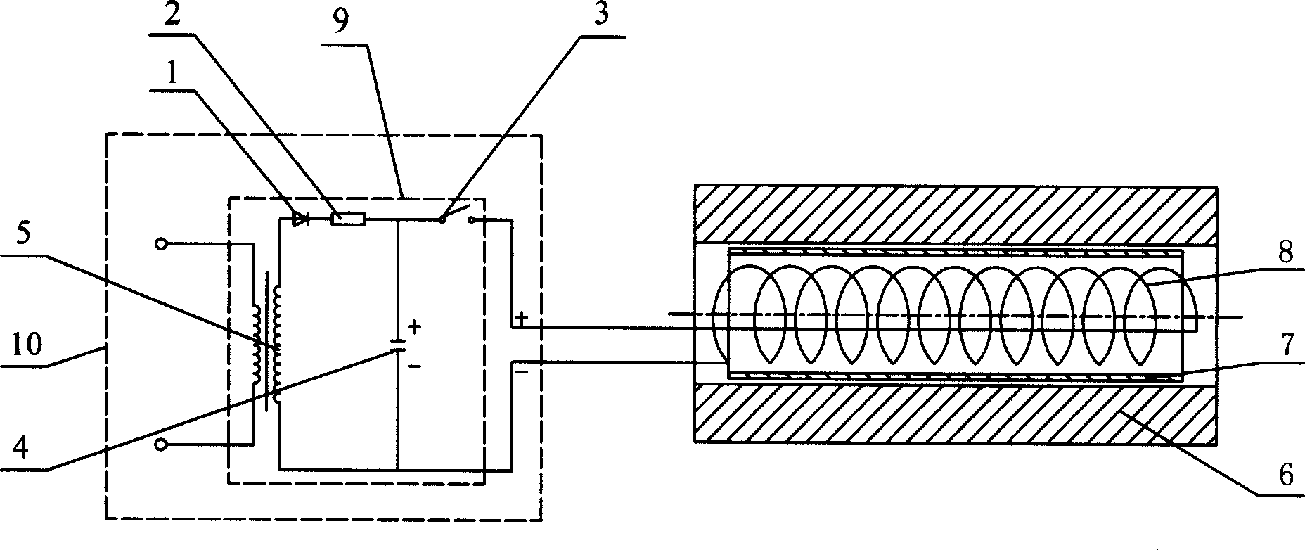
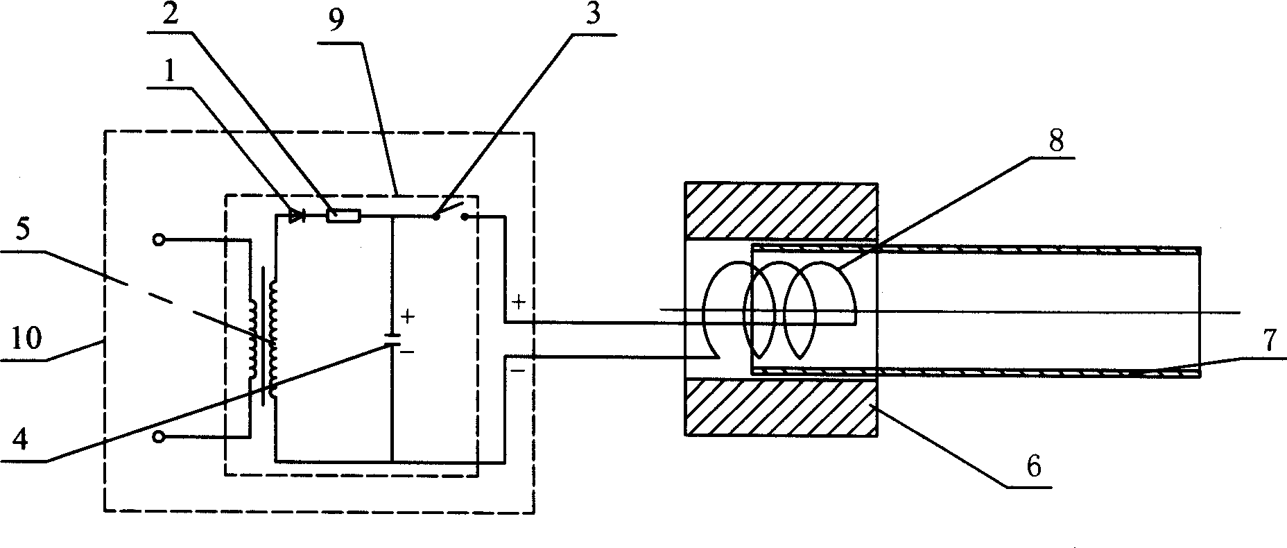
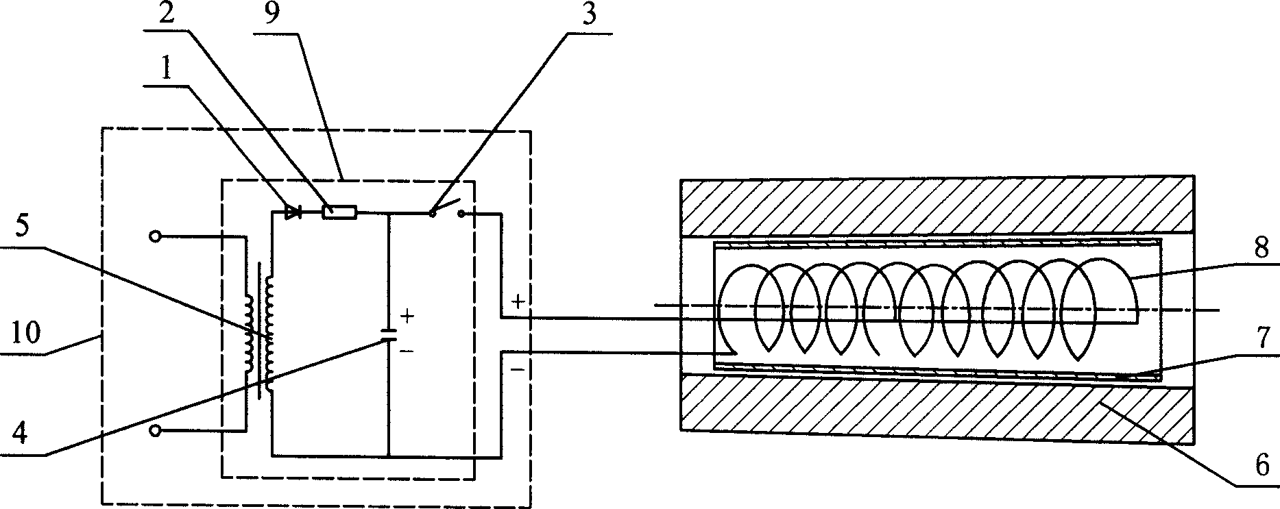
[0010] Specific implementation mode one: combine Figure 1-Figure 4 Describe this embodiment, the method step of this embodiment is:

[0011] Step 1: Place the metal thin-walled cylindrical part 7 or the port of the metal thin-walled cylindrical part 7 in the high-precision shaping mold 6, and place the magnetic pulse processing coil 8 in the metal thin-walled cylindrical part 7;

[0012] Step 2: use electromagnetic forming technology to correct the shape: connect the two terminals of the magnetic pulse processing coil 8 to the positive and negative poles of the magnetic pulse power supply 10, start the magnetic pulse power supply 10 at room temperature, and use the external power supply through a step-up transformer 5. The rectifier circuit 1 and the current-limiting resistor 2 charge the pulse capacitor bank 4. At this time, the air gap switch 3 is not turned on; when the pulse capacitor bank 4 stores enough electric energy and reaches the working voltage, close the air gap ...

specific Embodiment approach 2

[0013] Specific implementation mode two: combination figure 1 and figure 2 Describe this embodiment, the difference between this embodiment and specific embodiment 1 is: the magnetic pulse processing coil 8 described in step 1 of this embodiment is a cylindrical solenoid coil made of T3 copper wire with a rectangular cross section. , The coil turns are insulated with epoxy resin and glass cloth, and the coil skeleton is a glass cloth epoxy resin laminated rod. With such setting, the generated pulse magnetic pressure is greater and the machining accuracy is higher.

specific Embodiment approach 3

[0014] Specific implementation mode three: combination figure 1 and figure 2 Describe this embodiment, the difference between this embodiment and the specific embodiment one is: the metal thin-walled tubular part 7, the high-precision shape correction mold 6 and the magnetic pulse processing coil 8 described in the step one of the present embodiment are the same axis. With such an arrangement, the metal thin-walled cylindrical part 7 is more evenly stressed and has higher machining accuracy.


PUM

PropertyMeasurementUnit
Wall thicknessaaaaaaaaaa
Outer diameteraaaaaaaaaa
Diameteraaaaaaaaaa

Abstract

The invention discloses a method for improving roundness of a metal thin-wall cylindrical workpiece by pulsed magnetic pressure, and relates to a method for improving roundness of a metal thin-wall cylindrical workpiece. The method solves the problems that the existing cylindrical workpiece shape correction method has the disadvantages of complex mechanism and die, uneasy operation and low accuracy of shape correction, and the existing cylindrical workpieces have the disadvantages of easy wearing surface, residual stress, short service life, difficult sealing, high cost and difficult operation, both of which are not favorable for the small-batch and diversified development trend. The method comprises the following steps: step one: the metal thin-wall cylindrical workpiece is arranged in a high-accuracy shape correction die, and magnetic impulse processed coils are placed in the cylindrical workpiece; step two: a high-frequency pulse capacitor bank is used for discharging the magnetic pulse processing coils, high-frequency pulse acts on the cylindrical workpiece to cause the cylindrical workpiece to generate high-speed deformation and generate impact contact and adhere to the die. The invention has the advantages of simple mechanism and die, high machining accuracy, long service life and low cost, and is favorable for the small-batch and diversified development trend, etc.

Description

technical field [0001] The invention relates to a method for improving the roundness of a thin-walled cylindrical part, which belongs to the technical fields of manufacturing and processing of automobiles, aviation and aerospace. Background technique [0002] The cabins, fuel tanks, storage tanks and nozzles used in missiles, satellites, aircraft and other aerospace vehicles are mostly aluminum alloy cylindrical and special-shaped pipe fittings, which are usually processed by spinning process. On the one hand, due to the limited precision of spinning processing, it is impossible to meet the accuracy requirements of the drawings, and the product qualification rate is low and the use of out-of-tolerance occurs, which affects the subsequent processing and use performance of the product; on the other hand, considering the needs of structural installation and functional requirements, many The cylindrical part is subjected to a welding process. Due to the deformation caused by we...

Claims


Application Information

Patent Timeline
IPC IPC(8): B21D26/14
Inventor 李春峰于海平江洪伟赵志衡
Owner HARBIN INST OF TECH
Learn More