Fluid distributing valve, distributing valve combination unit and distributing system using the distributing valve

A fluid distribution valve and valve body technology, applied in distribution devices, engine components, engine lubrication, etc., can solve problems such as waste of lubricating oil, pollution of the working environment, insufficient pressure, etc., to avoid normal failures, and strong adaptability to impurities. , Set the effect of simple structure

Inactive Publication Date: 2009-03-18
张淑敏
View PDF1 Cites 11 Cited by
  • Summary
  • Abstract
  • Description
  • Claims
  • Application Information

AI Technical Summary

Problems solved by technology

2. There are two oil supply circuits in the system. Compared with the single-line oil distribution system and oil distribution device, the system is not easy to collapse, but the oil distribution valve in this system is easy to cause the oil distribution valve near the oil pump to withstand high pressure and the distance Insufficient pressure of the far oil distribution valve of the oil pump
The lubrication system using solenoid valves has the following disadvantages: 1. Solenoid valves are prone to normally-on failures, especially in lubrication systems with many lubrication points and many solenoid valves, as long as one solenoid valve has a normally-on failure, It will cause the waste of lubricating oil and the reduction of system oil pressure. At the same time, the excess grease will leak out and pollute the working environment.
2. The solenoid valve is generally large in size, and the lubrication system generally requires a small solenoid valve. The small size of the solenoid valve results in limited magnetic force, which makes the solenoid valve prone to blockage and affects the normal operation of the lubrication system.
The advantage of this kind of valve is that there is no excessively narrow part of the oil circuit, it has strong adaptability to impurities mixed in the grease, it has a long service life, and it is not easy to be blocked, but at the same time, this kind of valve also has its disadvantages: this kind of valve itself cannot control the oil In order to control the amount of oil supplied by the lubricating system using this valve, a solenoid valve is installed on the grease input pipeline of this valve, and the amount of oil (grease) supplied is adjusted by controlling the opening time of the solenoid valve.
However, considering the change of the solenoid valve switch time and the pressure of the main oil pipe of the system and the viscosity change of the lubricating oil, this device can actually only control the approximate amount of lubricating oil, but cannot accurately control the amount of lubricating oil.
At present, there is no oil separation device on the market that has the advantages of strong adaptability to the above-mentioned impurities, long service life, and no jamming, and can accurately control the amount of lubricating oil.

Method used


Image

  • Fluid distributing valve, distributing valve combination unit and distributing system using the distributing valve
  • Fluid distributing valve, distributing valve combination unit and distributing system using the distributing valve
  • Fluid distributing valve, distributing valve combination unit and distributing system using the distributing valve

Examples


Embodiment 1

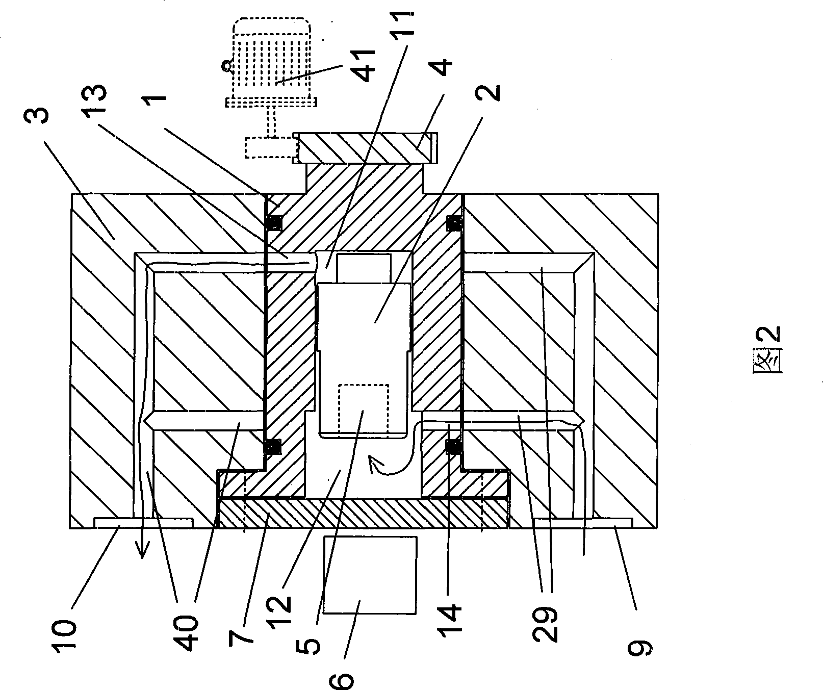
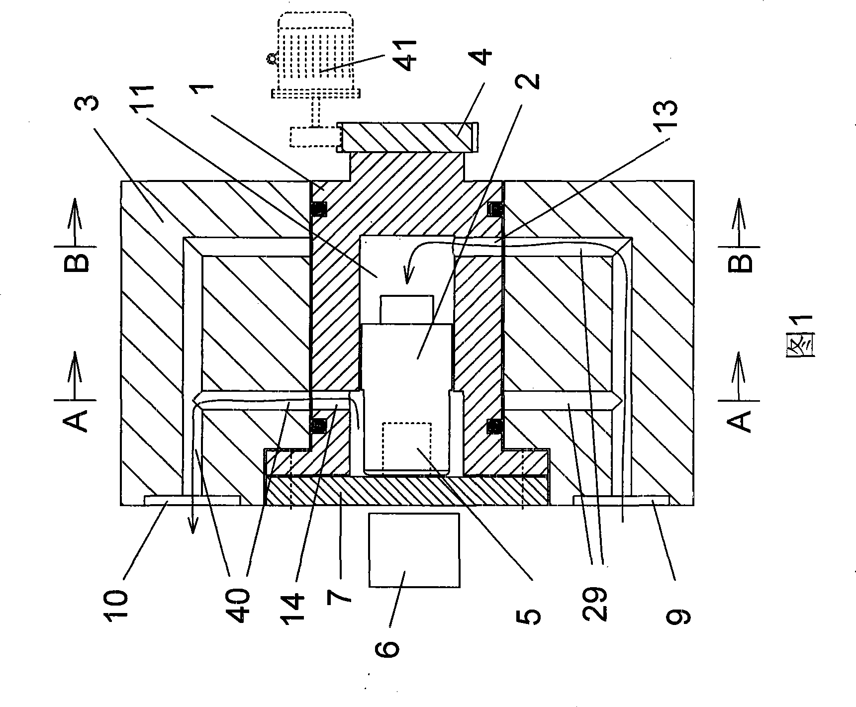
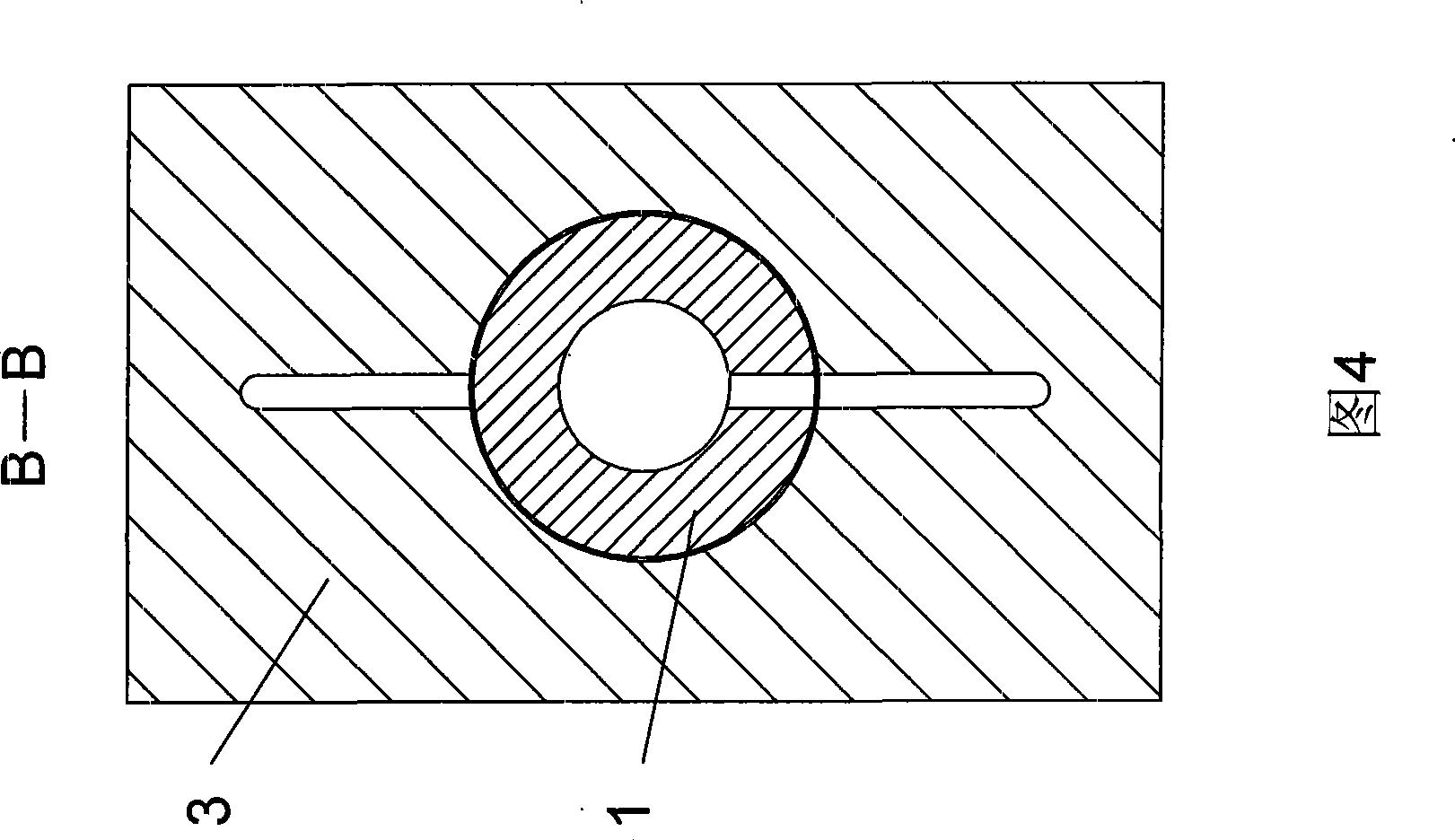
[0048] As shown in Figures 1 and 2, the fluid distributing valve of this embodiment includes a valve body 3, which is provided with a rotatable valve core 1 connected to an external drive device 41 through a transmission member 4, and a transmission member 4 Set on the right end of the valve core 1, the left end of the valve core 1 is closed in the valve body 3 by the end cover 7. The spool 1 is provided with a cavity, and the valve body 3 is also provided with an oil inlet valve body channel 29 and an oil outlet valve body channel 40 respectively opened on the surface of the valve body 3, and the cavity of the spool 1 is also slidably and sealingly connected with The cavity is divided into two parts, the first cavity 12 and the second cavity 11; the second cavity 11 is selectively connected to the oil outlet valve body channel 40 or the oil inlet valve body channel through the second valve core channel 13 29. Opposite to the communication direction of the second cavity 11 , ...

Embodiment 2

[0056]As shown in Figure 7, the difference between this embodiment and Embodiment 1 is that the plunger stroke detection device is an indicator rod 15 with one end fixedly connected to the plunger 2 and the other end protruding from the end cap 7, and an indicator rod 15 arranged on the valve body. 3 outer travel switches 16. A travel switch 16 is set at the left extreme position of the left end of the indicating rod 15 .

[0057] When the plunger 2 moves leftward or rightward with the indicating rod 15 and reaches the limit position, the operator can confirm the stroke position of the plunger 2 by observing the movement position of the indicating rod 15 . Of course, when the indicator rod 15 reaches the left limit position, it presses and triggers the travel switch 16 and makes it output the travel signal of the plunger 2 to the control system.

Embodiment 3

[0059] As shown in Figure 8 and Figure 9, the difference between this embodiment and Embodiment 1 is that there is no first spool channel 14 communicating with the first cavity 12, and a reset element is arranged in the first cavity 12 , The return element is a return spring 19, one end of the return spring 19 is press fit with the left end face of the plunger 2 and the other end is press fit with the end cap 7. Of course, the press fit between the above-mentioned spring 19 and the end cap 7 and the left end surface of the plunger 2 can also be a fixed connection. Due to the use of the spring 2, the fluid distribution valve of this embodiment has special requirements when in use, that is, the oil (fat) pressure at the oil inlet 9 of the valve body is greater than that formed by the elastic force of the spring 19 on the cross section of the plunger 2. The pressure formed by the elastic force of the spring 19 on the cross-section of the plunger 2 is greater than the back pressur...


PUM


Abstract

The invention discloses a fluid distributing valve, which comprises a valve body, wherein the inside of the valve body is provided with a rotatable valve core in driving connection with an external drive device, the inside of the valve core is provided with a cavity, the inside of the valve body is further provided with an oil inlet valve body passage and an oil outlet valve body passage the openings of which are positioned on the surface of the valve body, the valve core is provided with a valve core passage corresponding to the oil inlet valve body passage and the oil outlet valve body passage inside the valve body, and the inside of the cavity of the valve core is hermetically and slidably connected with a plunger which divides the cavity into a first cavity and a second cavity; and the second cavity selects to be communicate with the oil outlet valve body passage or the oil outlet valve body passage through the second valve core passage. The fluid distributing valve adopts the structure that the inside of the cavity of the rotatable valve core is provided with the plunger which divides the cavity into two parts, has the advantages of strong adaptability to impurities, long service life and difficult blockage brought by the rotatable valve core of the rotary circulating-distributing valve in the document number of 200420029881.1, and can accurately control the amount of the lubricant (the grease lubricant).

Description

technical field [0001] The invention relates to the field of fluid distribution, in particular to a fluid distribution valve, a distribution valve combination unit using the fluid distribution valve, and a distribution system using the fluid distribution valve. Background technique [0002] At present, in metallurgy, mining, building materials, power generation and other industries and large-scale construction machinery, the original oil box oil supply method is gradually eliminated in these application fields, and the distribution devices and systems of lubricating oil and grease that are widely used mainly include: The following two types: 1. Single-line oil distribution system and single-line oil distribution valve; 2. Double-line oil distribution system and double-line oil distribution valve. [0003] The disadvantage of single-line oil separation system and single-line oil separation valve is obvious, that is, as long as one lubrication point is blocked, the circulation...

Claims


Application Information

Patent Timeline
Patent Type & Authority Applications(China)
IPC IPC(8): F16N25/04
Inventor 职子立职建军马秀叶汪任初张卫华杨俊德沈木峰张同军王欣职毛留
Owner 张淑敏
Why Eureka
Try Eureka