
Evaporation cooling construction for turbine generator rotor winding

A steam turbine generator and rotor winding technology, applied in the shape/style/structure of winding conductors, manufacturing motor generators, motor components, etc., can solve the problem of high processing cost, difficult industrial production application, corrosion of conductors and insulating materials, etc. problems, to achieve the effect of increasing capacity and efficiency, reducing flow resistance and smooth flow

Active Publication Date: 2011-08-03
INST OF ELECTRICAL ENG CHINESE ACAD OF SCI
View PDF1 Cites 0 Cited by
  • Summary
  • Abstract
  • Description
  • Claims
  • Application Information

AI Technical Summary

Problems solved by technology

The main disadvantage of this patent is that water is used as the cooling medium, and there is a problem of corrosion of large shafts, conductors, and insulating materials by water and steam.
The water quality requirements are also high, otherwise scaling and precipitation will occur; second, the wire structure uses a special concave-shaped open wire, which has high processing costs and complicated installation processes. It is difficult to ensure that the wires are not deformed during the winding process of the rotor winding. Applied in industrial production

Method used


Image

  • Evaporation cooling construction for turbine generator rotor winding
  • Evaporation cooling construction for turbine generator rotor winding
  • Evaporation cooling construction for turbine generator rotor winding

Examples


Embodiment Construction

[0014] The present invention will be further described below in conjunction with the accompanying drawings and specific embodiments.

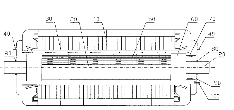
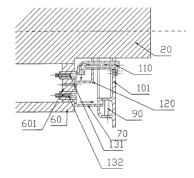
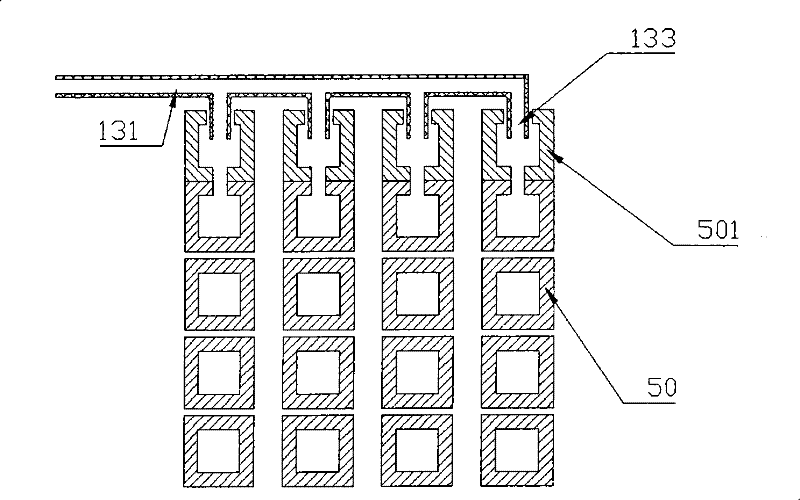
[0015] Overall structure of the present invention is as figure 1 shown. The inner wall of the stator 10 is separated from the rotor 20 by an isolation sleeve 30 , and an air gap is formed between the inner surface of the isolation sleeve 30 and the outer surface of the rotor 20 . The rotor 20 is a hidden pole rotor, and its shape is an elongated cylinder. The circumference of the iron core of the rotor 20 is milled with slots, and the rotor windings 50 are embedded in these slots. The rotor winding 50 is a concentric winding, wound with a hollow copper wire, and the winding is fastened in the slot by a non-magnetic slot wedge 202 . In order to protect and fasten the end of the rotor winding 50, there are guard rings 60 on both sides of the rotor 20, one end of the guard ring 60 is shrunk onto the end of the rotor body, and the other end is f...


PUM


Abstract

The invention relates to an evaporating-cooling structure of a turbo generator rotor winding, wherein a gas-eliminator hole (504) is arranged on the straight-line portion of a rotor winding hollow conductor (502), and a radial exhaust steam passage (151) is arranged on a slot insulation (150) which is corresponding to the gas-eliminator hole (504). Cooling medium steam is discharged through the gas-eliminator hole (504) and the radial exhaust steam passage (151), flowing resistance is reduced. Overflow devices are arranged in each layer of a rotor coil (50), cooling medium is enabled to be evenly distributed, and the evaporating-cooling structure lowers the radial temperature difference of the rotor winding when cooling is reinforced by the rotor. The evaporating-cooling structure enablesthe cooling effect of the rotor winding to be better, and can relatively improve the capacity and the efficiency of a turbo generator.

Description

technical field [0001] The invention relates to an evaporative cooling structure for the rotor winding of a steam turbine generator. Background technique [0002] Although the voltage of the rotor winding of the turbogenerator is not high, the volume is compact and the heat is concentrated. Currently, the commonly used cooling methods include air cooling, hydrogen cooling, and water cooling. The gas cooling method means that the rotor winding is made of hollow copper wire, and air or hydrogen is pressed into the side holes and longitudinal grooves milled at both ends of the winding by a high-pressure fan, and flows out from the middle or the other side. This method requires a high-pressure multi-stage fan, with large ventilation loss and uneven temperature distribution. The principle of rotor water cooling is that the cooling water is introduced into the high-speed rotating rotor through the water inlet device, circulates and absorbs heat inside the rotor coil, and then the...

Claims


Application Information

Patent Timeline
Patent Type & Authority Patents(China)
IPC IPC(8): H02K3/24H02K9/00H02K15/00
Inventor 侯哲顾国彪
Owner INST OF ELECTRICAL ENG CHINESE ACAD OF SCI
Learn More