Check patentability & draft patents in minutes with Patsnap Eureka AI!

Secondary sampling current control synchronous rectifying driver circuit

A technology of synchronous rectification and sampling current, applied in the direction of converting AC power input to DC power output, electrical components, output power conversion devices, etc. The effect of improving efficiency, small size and low cost

Active Publication Date: 2009-03-18
INVENTRONICS HANGZHOU
View PDF0 Cites 14 Cited by
  • Summary
  • Abstract
  • Description
  • Claims
  • Application Information

AI Technical Summary

Problems solved by technology

Therefore, the number of transformers is large, the cost is high, and the PCB (printed circuit board) wiring is difficult, the output line of the transformer is too thick, the processing is complicated, and the cost is high

Method used


Image

  • Secondary sampling current control synchronous rectifying driver circuit
  • Secondary sampling current control synchronous rectifying driver circuit
  • Secondary sampling current control synchronous rectifying driver circuit

Examples


Embodiment Construction

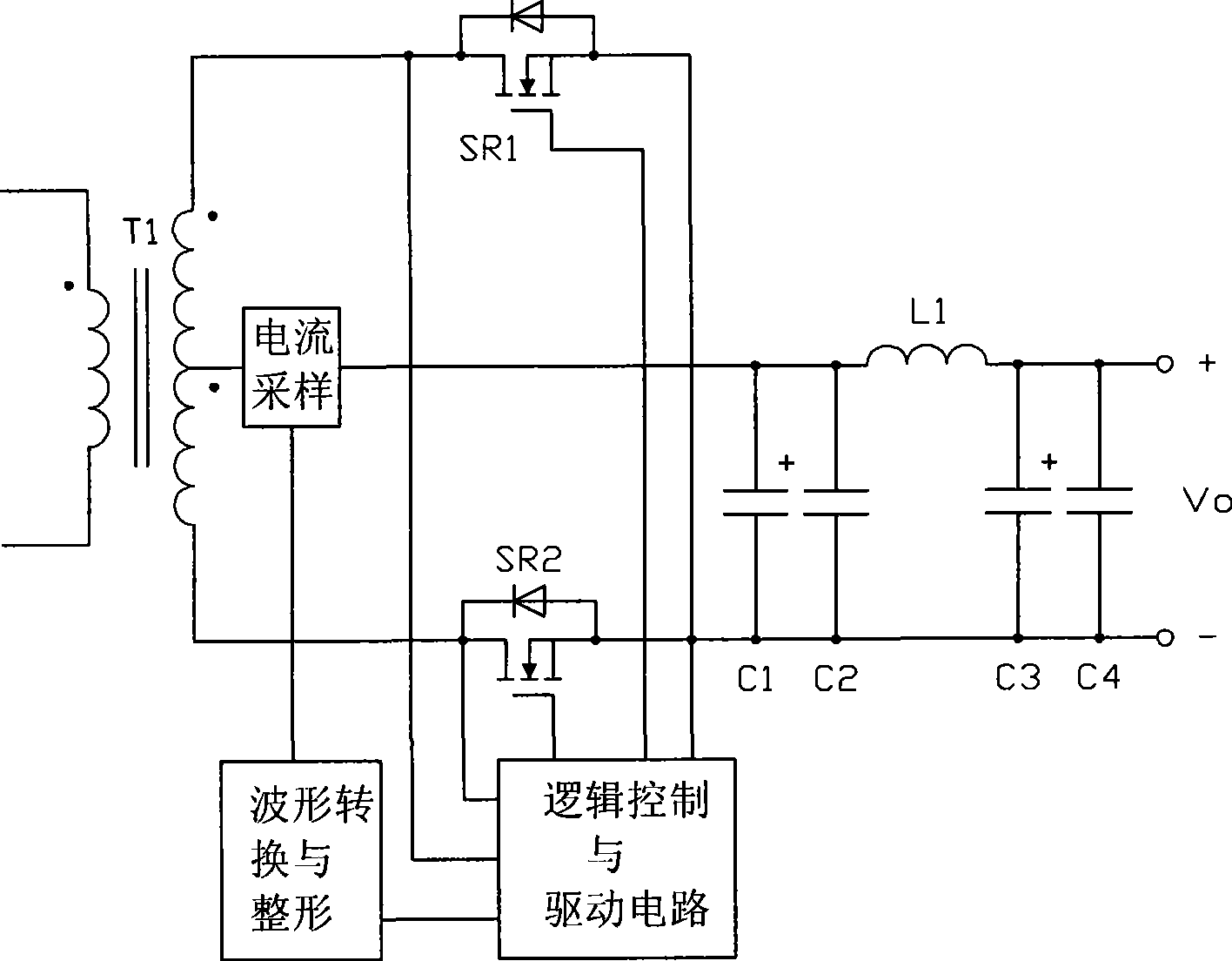
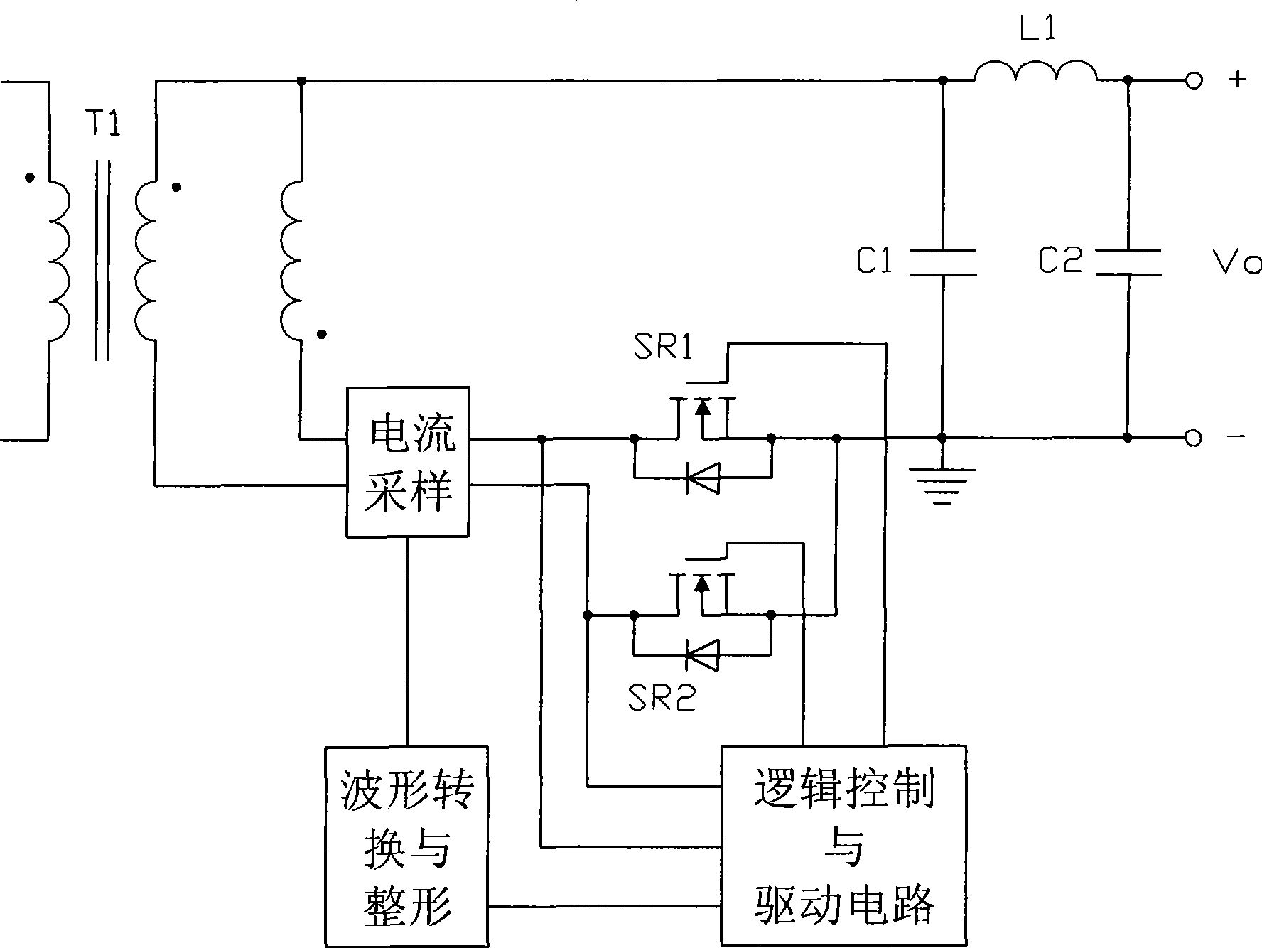
[0026] refer to figure 2 , the circuit block diagram of the secondary side sampling current control synchronous rectification drive circuit of the present invention, including a current sampling circuit, a waveform conversion and shaping circuit, a logic control and a power drive circuit:

[0027] The current sampling circuit samples the current at the center tap of the secondary side of the transformer through a transformer, and outputs it to the waveform conversion and shaping circuit;

[0028] The waveform conversion and shaping circuit converts the received sampling current signal into a voltage signal and shaping it, its input is connected to the secondary side of the current sampling circuit, and its output is connected to the logic control and power drive circuit;

[0029] The logic control and power drive circuit divides the received voltage signal after shaping into two drive signals through logic control, and then drives the corresponding synchronous rectifiers resp...


PUM


Abstract

The invention discloses a secondary side sampling current control synchronous rectification drive circuit, which comprises a current sampling circuit, a wave pattern transformation and shaping circuit, and a logic control and power drive circuit. The drive circuit is characterized in that firstly, a current transformer samples center terminal current on the secondary side of a transformer, secondly, a driving voltage signal is obtained through the wave pattern transformation and shaping circuit and is output, then, the driving voltage signal passes through the logic control and power drive circuit and then drives a rectifying tube. The circuit of the invention is comparatively simple, has small volume, high efficiency, lower cost, easy realization and convenient use, and is an invention with high practical values and economic benefits. The center tapped sampling synchronous rectification technique in the invention can be combined with an energy feedback circuit in a mutual inductor and is applicable to various voltage output application occasions.

Description

technical field [0001] The invention relates to a synchronous rectification drive circuit. More specifically, the present invention relates to a synchronous rectification drive circuit controlled by primary side sampling current. Background technique [0002] With the rapid development of information technology and the increase of the operating frequency of various integrated circuits, in order to reduce the power consumption of the circuit, the power supply voltage will be further reduced to below 1V, and there are more and more low-voltage and high-current power supplies. When the output voltage drops, due to the high conduction voltage drop of the diode (fast recovery diode FRD or ultra-fast recovery diode SRD can reach 1.0-1.2V, even if a low-drop Schottky diode is used, it will generate about 0.6V voltage drop,), it will reduce the efficiency of the converter. The emergence of synchronous rectification technology, the development of synchronous rectification devices a...

Claims


Application Information

Patent Timeline
Patent Type & Authority Applications(China)
IPC IPC(8): H02M7/217
Inventor 华桂潮吴新科
Owner INVENTRONICS HANGZHOU
Features
  • R&D
  • Intellectual Property
  • Life Sciences
  • Materials
  • Tech Scout
  • Unparalleled Data Quality
  • Higher Quality Content
  • 60% Fewer Hallucinations
Learn More