Elevator controller
A technology of elevator control device and braking device, which is applied in the direction of motor generator control, control system, electrical components, etc., can solve the problems of rising manufacturing cost of elevator control device, etc., and achieve the effect of realizing regenerative braking function
- Summary
- Abstract
- Description
- Claims
- Application Information
AI Technical Summary
Problems solved by technology
Method used
Image

Examples
no. 1 approach
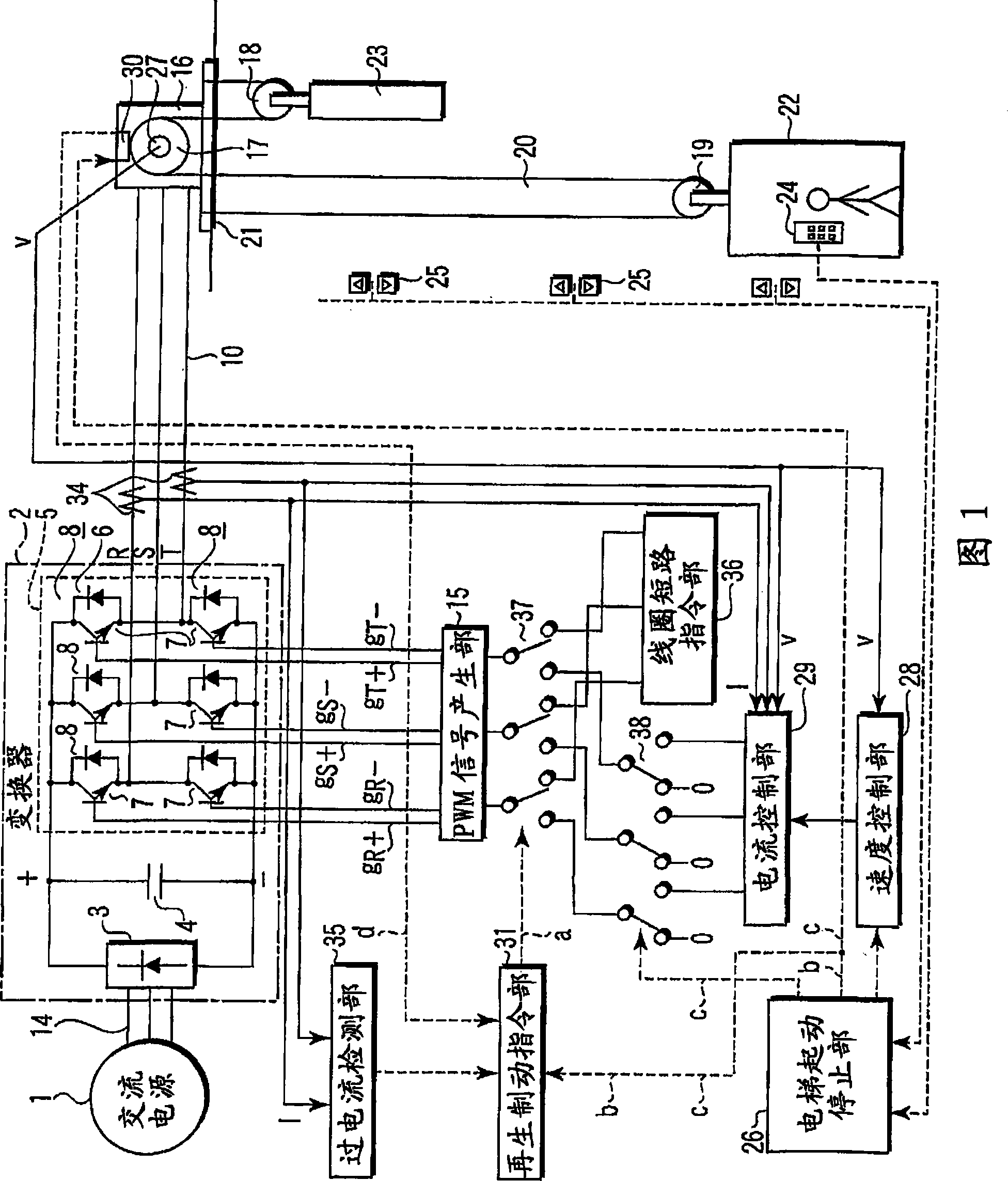
[0052] Fig. 1 is a schematic configuration diagram of an elevator control device according to a first embodiment of the present invention. The same reference numerals are assigned to the same parts as those of the conventional elevator control device shown in Fig. 12, and detailed description of overlapping parts will be omitted.
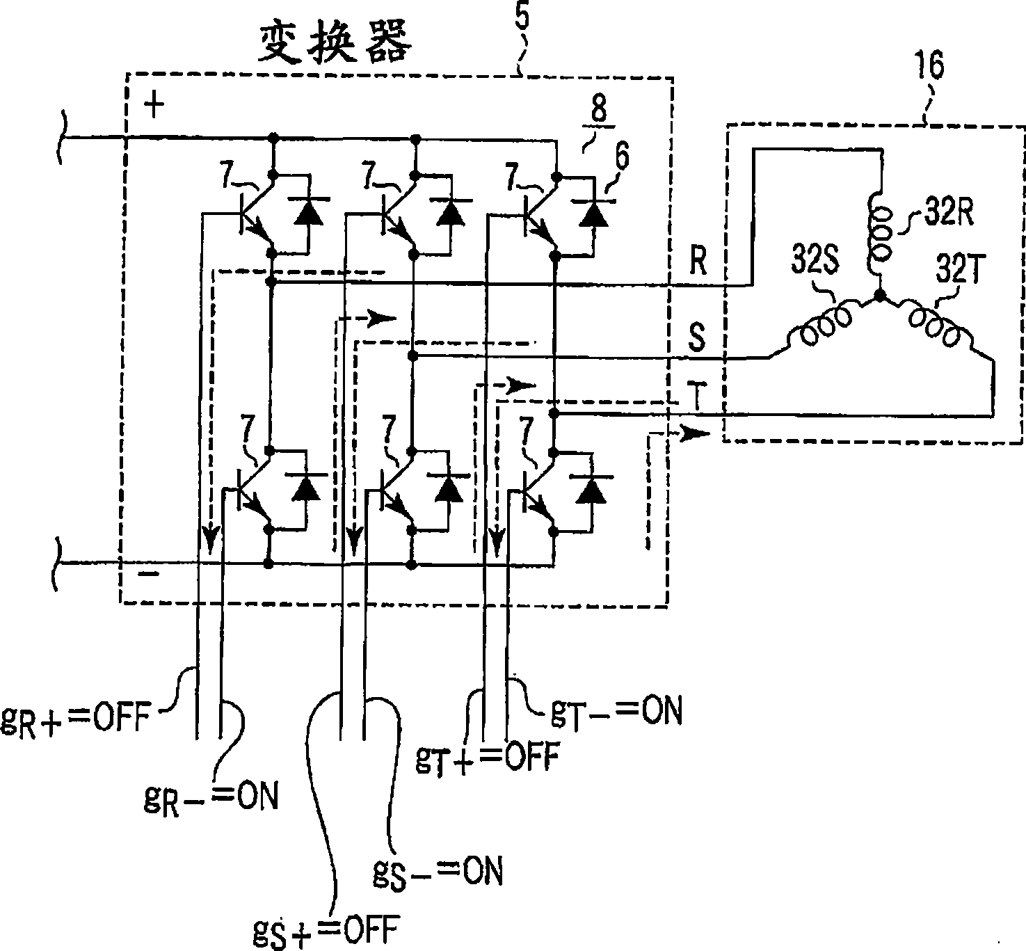
[0053] The three-phase AC power supplied from the AC power source 1 through the wire 14 is full-wave rectified by the rectifier 3 of the power conversion unit 2 into DC power. The DC power output from the rectifier 3 absorbs fluctuations in the smoothing capacitor 4 and supplies it to the inverter 5 . In this converter 5, six parallel circuits 8 in which diodes 6 and switching elements 7 are connected in parallel are bridge-connected to each other.
[0054] Furthermore, each PWM signal g output from the PWM (Pulse Width Modulation) signal generating section 15 R+ , g R- , g S+ , g S- , g T+ , g T- The power-on / off control of each switching el...
no. 2 approach
[0085] Fig. 6 is a schematic configuration diagram of an elevator control device according to a second embodiment of the present invention. The same reference numerals are assigned to the same parts as those of the elevator control device according to the first embodiment of the present invention shown in FIG. 1 , and detailed description of overlapping parts will be omitted.
[0086] In the elevator control device of the second embodiment, a speedometer 27 is attached to the permanent magnet synchronous motor 16 . The speed v detected by the speedometer 27 is input to the speed control unit 28 , the current control unit 29 and the deceleration detection unit 39 .
[0087] The deceleration detection unit 39 calculates the deceleration dv by time-differentiating the input velocity v. In addition, the overcurrent detection unit 35 in the first embodiment is eliminated. Therefore, the current I of the electric wire 10 is detected by the ammeter 34 and output only to the current...
no. 3 approach
[0099] Figure 9 It is a schematic configuration diagram of an elevator control device according to a third embodiment of the present invention. The same reference numerals are assigned to the same parts as those in the elevator control device according to the first embodiment of the present invention shown in FIG. 1 , and detailed description of overlapping parts will be omitted.
[0100] In the elevator control device according to the third embodiment, a power failure detection unit 40 for detecting a power failure of the AC power supply 1 is provided on the electric wire 14 for supplying three-phase current from the AC power supply 1 to the power conversion unit 2 . Furthermore, there is provided a coil short-circuit instruction unit 43 during a power failure, which outputs PWM signals g having the following signal levels to each switching element 7 of the inverter 5 for regenerative braking of the motor 16 when a power failure occurs: R+ , g R- , g S+ , g S- , g T+ , ...
PUM
 Abstract
Description
Claims
Application Information
 - R&D
- Intellectual Property
- Life Sciences
- Materials
- Tech Scout
- Unparalleled Data Quality
- Higher Quality Content
- 60% Fewer Hallucinations
Browse by: Latest US Patents, China's latest patents, Technical Efficacy Thesaurus, Application Domain, Technology Topic, Popular Technical Reports.
© 2025 PatSnap. All rights reserved.Legal|Privacy policy|Modern Slavery Act Transparency Statement|Sitemap|About US| Contact US: help@patsnap.com