Ferritic steel barrel butt-junction circular-seam hot-wire TIG multi-layer multipath welding method
A low-alloy steel, multi-layer and multi-channel technology, applied in welding equipment, heat treatment furnace, arc welding equipment, etc., can solve the problems of low deposition efficiency and long processing cycle, so as to improve processing quality, reduce processing cost, prevent The effect of slag accumulation
- Summary
- Abstract
- Description
- Claims
- Application Information
AI Technical Summary
Problems solved by technology
Method used
Image

Examples
specific Embodiment approach 1
[0025] Specific implementation mode 1: The specific process of the low-alloy steel cylinder butt circular seam hot wire TIG multi-layer multi-pass welding method described in this implementation mode is:
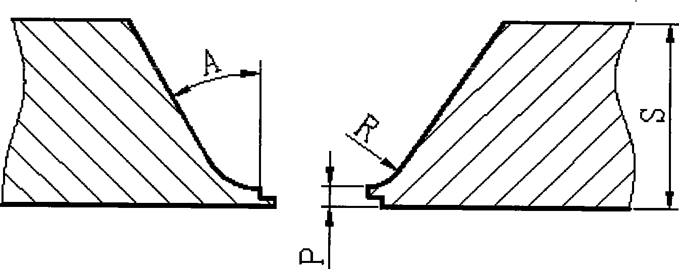
[0026] Step 1. Process the bevels of the end surfaces of the cylinders to be welded: respectively turn the welded end surfaces of the two cylinders to be welded into U-shaped bevels with blunt edges that cooperate with each other;
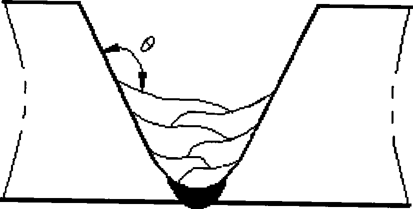
[0027] Step 2. Welding the U-shaped groove, which specifically includes the following steps:
[0028] Step 21. Pre-welding and preheating the two tubes to be welded: After assembling the two tubes to be welded in place, pre-weld and preheat the furnace. The heating temperature is 280-300°C, and the holding time is 120± 5 minutes to make the product heated evenly;
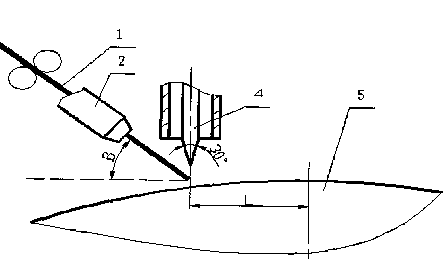
[0029] Step 22, the test piece processed in step 21 is released from the oven, put into the fixture of the automatic welding machine, adjust the relative position of the welding torch...
specific Embodiment approach 2
[0047] Specific embodiment 2: The difference between this embodiment and the specific embodiment is that the low-alloy steel cylinder butt ring seam hot wire TIG multi-layer multi-pass welding method is that the wall thickness S of the cylinder to be welded is 15mm- 50mm, the difference of the welding method is:
[0048] In the bottom welding process of step two or three, a welding wire with a diameter of Φ1.2mm is used, the welding current is 145A to 160A, the arc length is 3mm to 4mm, the corresponding voltage is 12V to 14V, and the speed is 120mm / min. The diameter is 4mm~5mm, the end angle of the tungsten pole is 30°~40°, the length of the tungsten pole protruding from the protective nozzle 3 is 6mm~8mm, the inner diameter of the protective nozzle 3 is 11mm, and the gas flow rate is 18L / min~22L / min, welding torch advance is 25mm~30mm,
[0049] Refer to Table 1 for the program parameter setting of TIG welding:
[0050] Table 1
[0051]
TORCH PREGAS
Torch ...
PUM
| Property | Measurement | Unit |
|---|---|---|
| Diameter | aaaaa | aaaaa |
| Tensile strength | aaaaa | aaaaa |
| Wall thickness | aaaaa | aaaaa |
Abstract
Description
Claims
Application Information
 - R&D
- Intellectual Property
- Life Sciences
- Materials
- Tech Scout
- Unparalleled Data Quality
- Higher Quality Content
- 60% Fewer Hallucinations
Browse by: Latest US Patents, China's latest patents, Technical Efficacy Thesaurus, Application Domain, Technology Topic, Popular Technical Reports.
© 2025 PatSnap. All rights reserved.Legal|Privacy policy|Modern Slavery Act Transparency Statement|Sitemap|About US| Contact US: help@patsnap.com