Multifunction downhole bottom ripping machine

An undercover machine and multi-functional technology, applied in underground transportation, underground mining, mechanically driven excavators/dredgers, etc., can solve the problems of high labor intensity, high hidden dangers of operation safety, low efficiency and other problems, and achieve safe and convenient movement and handling, large transmission torque and wide application range

Inactive Publication Date: 2009-03-25
TAIZHOU XINGDONG COAL MINING MACHINERY
View PDF0 Cites 19 Cited by
  • Summary
  • Abstract
  • Description
  • Claims
  • Application Information

AI Technical Summary

Problems solved by technology

[0002] When the coal mining face encounters a soft coal seam floor, manual undercover is required to maintain the height of the roadway as the working face advances. Even under normal operation, it is often necessary to manually clean the floating coal under the loader and belt conveyor to maintain normal production. The labor intensity of the workers is high. In the production process, a large number of materials and accessories are currently loaded and unloaded by manual chain hoists. The roots of the chain hoists need to be lowered to the shed or lifted by the anchor rod. Not only the workload is large, the efficiency is low, and the material is wasted. , the more important thing is that the manual operation below the root lifting point has a great potential safety hazard
During the installation of fully mechanized mining and caving working face equipment, the installation and unloading of the front and rear chutes are currently lifted and aligned by manual chain hoists. A total of 200-300 lifting anchors need to be drilled in the cutting hole of the working face, and the roof condition is poor. Sometimes it is necessary to step down from the shed to strengthen maintenance. There are also heavy physical labor, low efficiency, serious waste and potential safety hazards.

Method used


Image

  • Multifunction downhole bottom ripping machine
  • Multifunction downhole bottom ripping machine
  • Multifunction downhole bottom ripping machine

Examples


Embodiment Construction

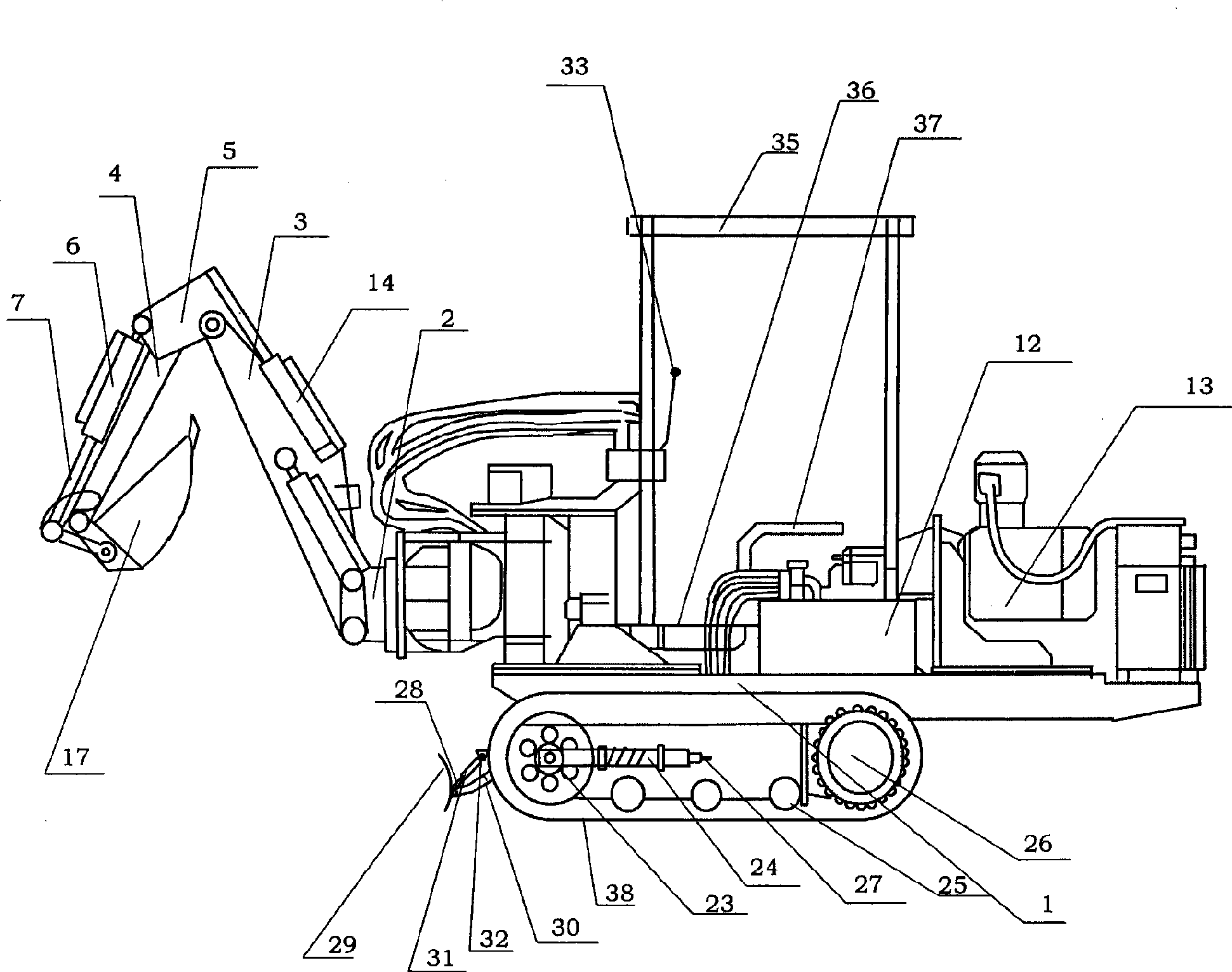
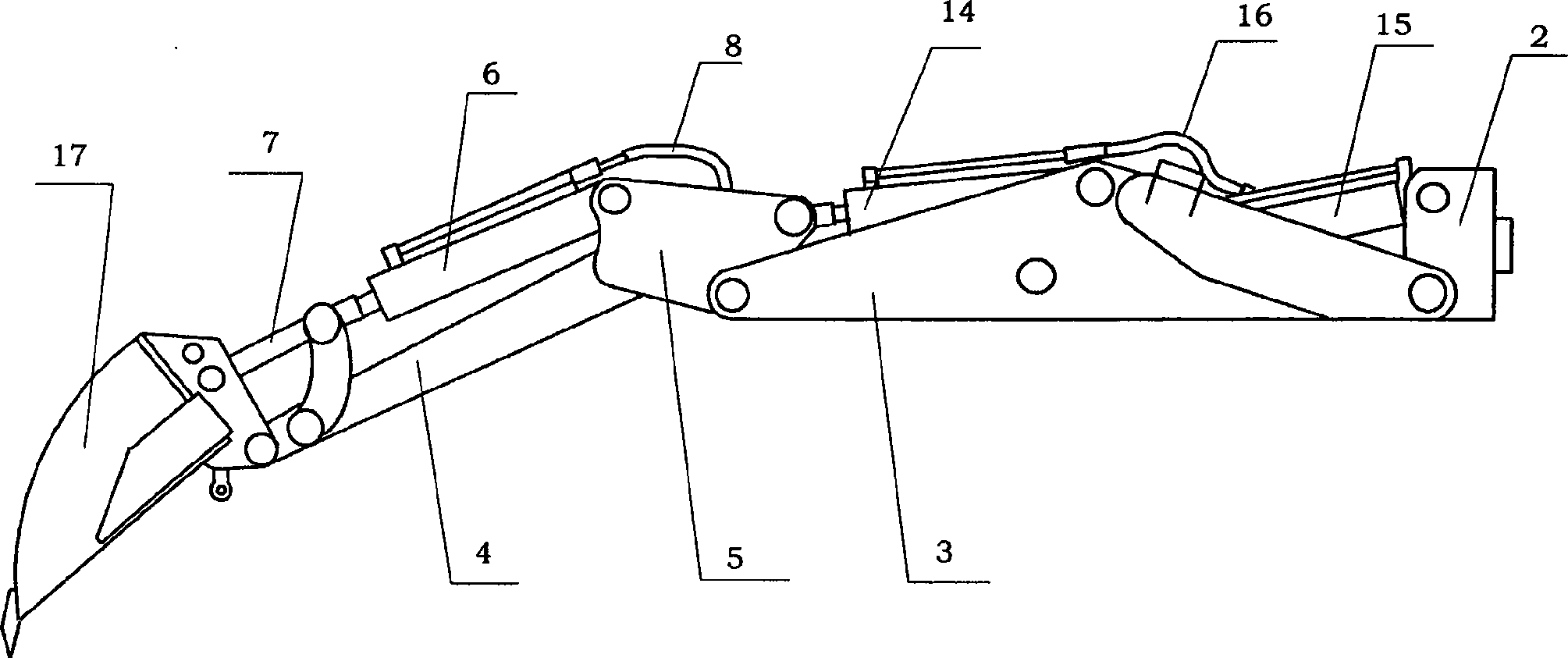
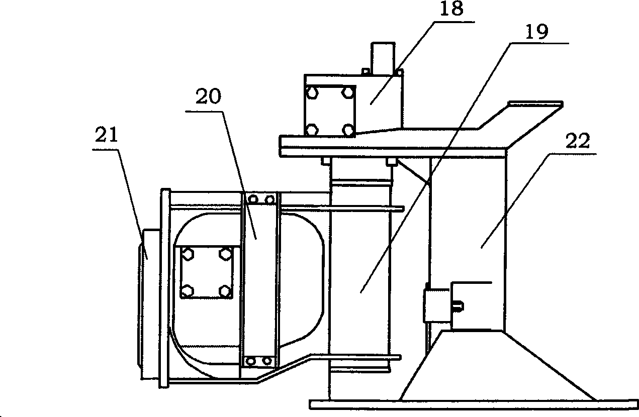
[0012] exist figure 1 , figure 2 , image 3 and Figure 4 Among them, the present invention is A multifunctional underground undercover machine, which includes a car body part and an actuator, and the car body part includes a workbench and a driving device 1 , walking gear and fuel tank 12, the top of fuel tank is provided with air filter and oil return pipe 11 and is connected, is provided with ceiling 35, step plate 36 and bottom stool 37 on the workbench, and walking gear is proposed to have assembled steel track 22, in The assembled steel crawler 22 is provided with a guide wheel 23, a tension cylinder 24, a support wheel 25, a travel motor 26, a guide wheel 23, and a tension cylinder 24 from front to back. One end of the tension cylinder 24 is connected to the guide wheel 23 connection, the other end is provided with an oil filling check valve 27, the driving device 13 is connected to the traveling device as a transmission, the worktable is connected to the traveli...


PUM


Abstract

The invention discloses a multi-functional underground dinting machine. The head part of a digging arm of the multi-functional underground dinting machine is connected with an operating head, while the tail part is provided with a support (2), a revolving device is arranged between the digging arm and a worktable, one end of a small arm (4) is rotationally connected with the operating head, while the other end is connected with a movable arm (5), a movable arm oil cylinder (6) is arranged above the small arm (4) and is communicated with an oil inlet pipe (10) and an oil return pipe (11) through a connecting pipe I(8) and an oil channel control valve (9) of an operating device, one end of a large arm (3) is rotationally connected with the movable arm (5), while the other end is rotationally connected with the revolving device, a large arm oil cylinder I(14) and a large arm oil cylinder II(15) are arranged above the large arm (3), and the large arm oil cylinder I(14) is communicated with the oil inlet pipe (10) and the oil return pipe (11) sequentially through a connecting pipe II(16), the large arm oil cylinder II(15) and the oil channel control valve (9) of the operating device.

Description

technical field [0001] The invention relates to a multifunctional underground undercover machine. Background technique [0002] When the coal mining face encounters a soft coal seam floor, manual undercover is required to maintain the height of the roadway as the working face advances. Even under normal operation, it is often necessary to manually clean the floating coal under the loader and belt conveyor to maintain normal production. The labor intensity of the workers is high. In the production process, a large number of materials and accessories are currently loaded and unloaded by manual chain hoists. The roots of the chain hoists need to be lowered to the shed or lifted by the anchor rod. Not only the workload is large, the efficiency is low, and the material is wasted. , the more important thing is that manual work below the root lifting point has a great potential safety hazard. During the installation of fully mechanized mining and caving working face equipment, the...

Claims


Application Information

Patent Timeline
Patent Type & Authority Applications(China)
IPC IPC(8): E21C41/16E21F13/00E21D20/00E02F3/96E02F3/28E02F3/76
CPCE21D9/1013E21D9/007E21D9/01
Inventor 许世东
Owner TAIZHOU XINGDONG COAL MINING MACHINERY
Why Eureka
Try Eureka