Evaporation chamber for inner container type evaporative cooling device

A technology of evaporative cooling and evaporation chamber, which is applied in the field of evaporation chamber and can solve the problems of increasing costs

Inactive Publication Date: 2009-04-01
北京博思利码科技有限公司
View PDF1 Cites 3 Cited by
  • Summary
  • Abstract
  • Description
  • Claims
  • Application Information

AI Technical Summary

Problems solved by technology

[0002] Chinese patent CN2824289 discloses a whole-system non-consumable refrigerant gravity cycle evaporative cooling device with switching power supply. The patent lists several structures of the evaporation chamber. Since the refrigerant has a certain p

Method used


Image

  • Evaporation chamber for inner container type evaporative cooling device
  • Evaporation chamber for inner container type evaporative cooling device
  • Evaporation chamber for inner container type evaporative cooling device

Examples


Embodiment Construction

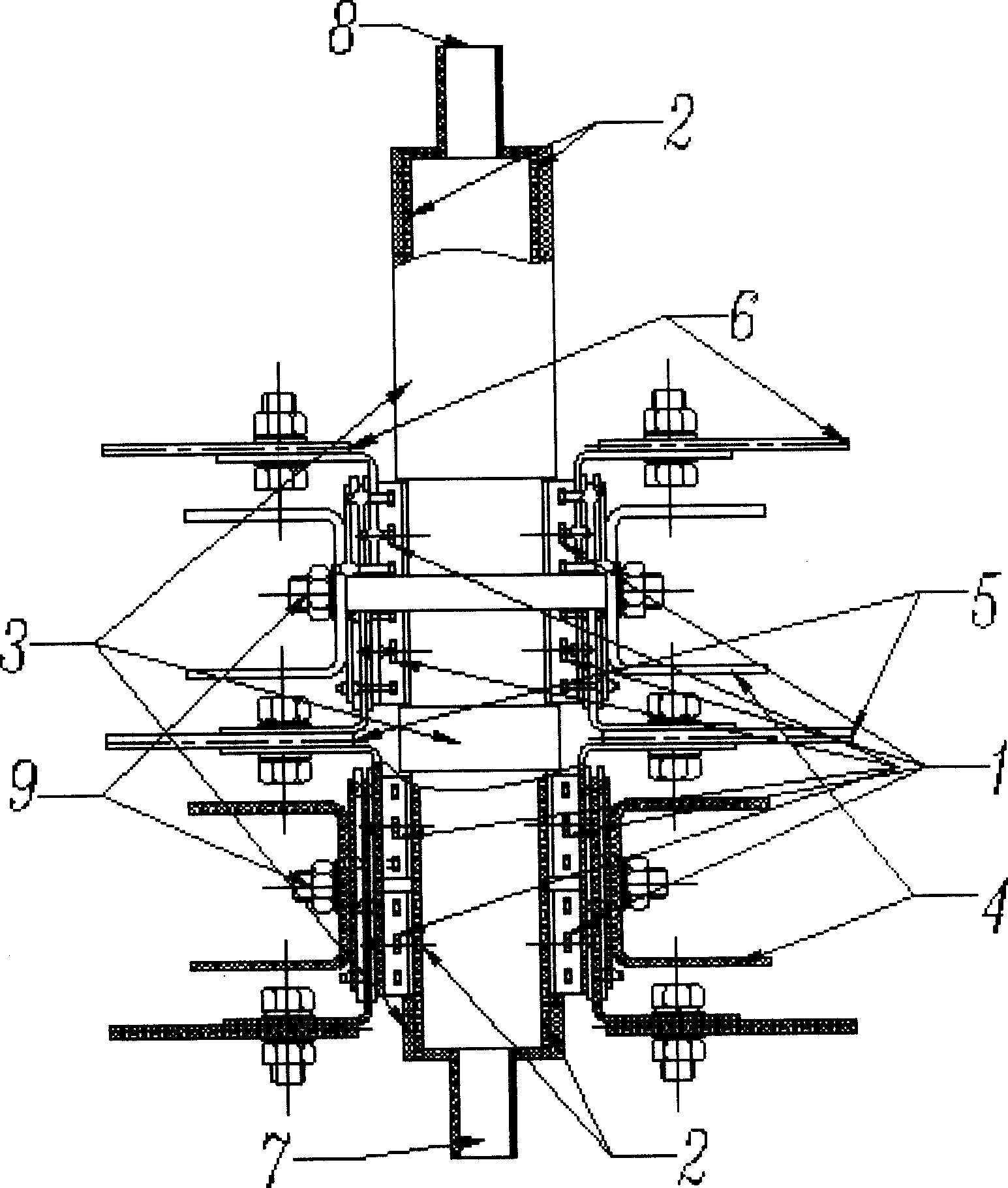
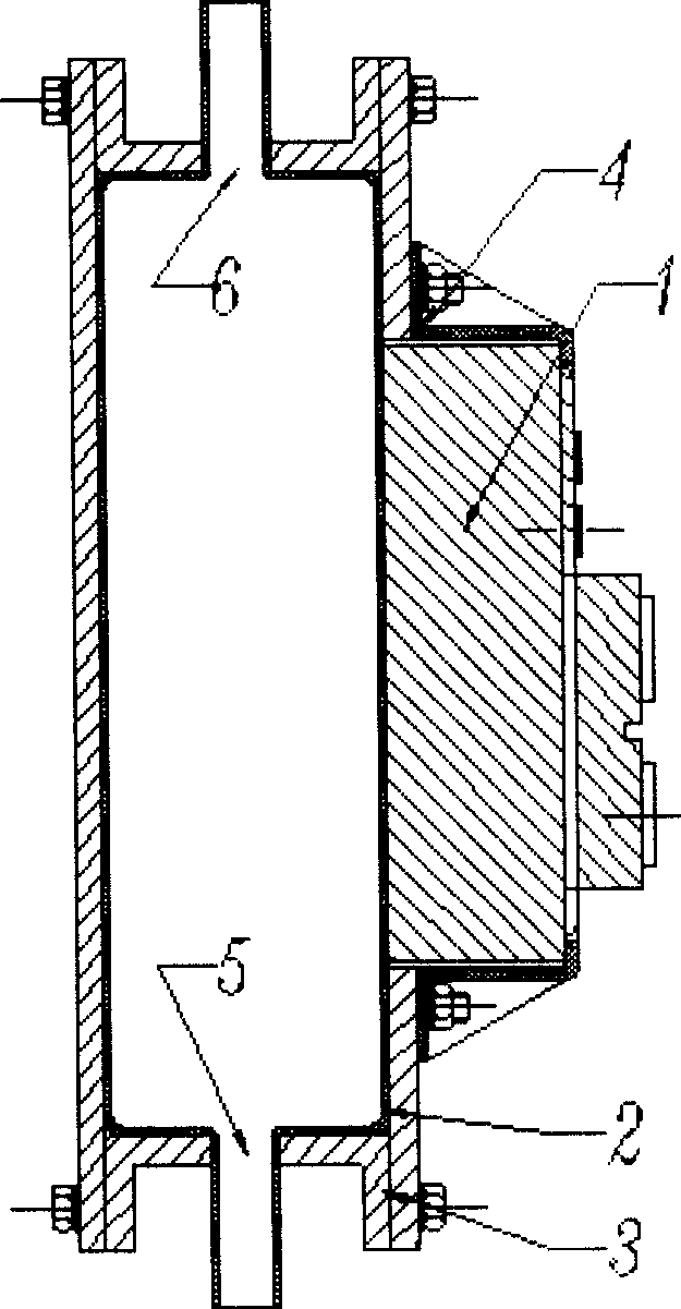
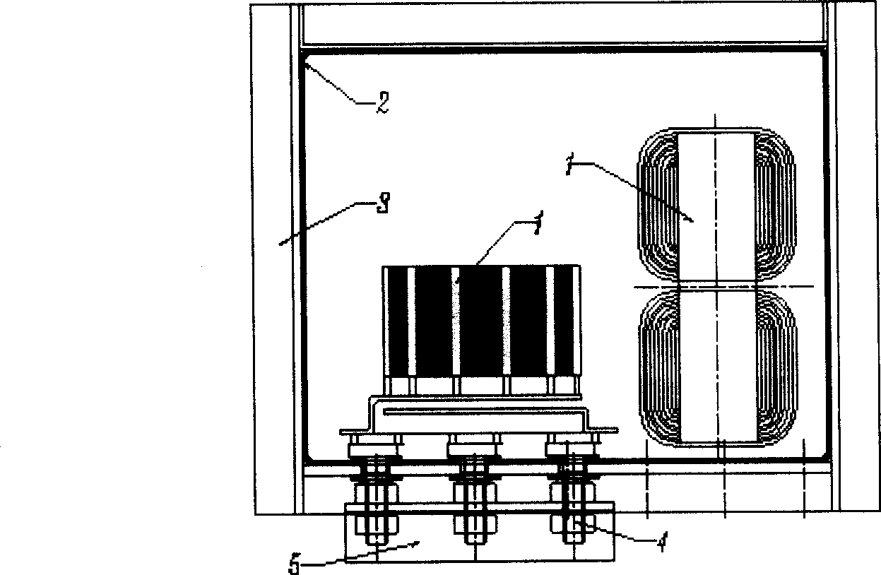
[0016] Figure (1) shows the structure of the evaporation chamber of a liner-type evaporative cooling device equipped with plastic-encapsulated semiconductor power devices. In the figure, 1 is a cooled semiconductor power device, 2 is an inner tank made of a thin metal plate, preferably a copper plate, and 3 is an outer jacket clamp, which is made of high mechanical strength metal such as steel, stainless steel and other materials. 4 is a metal pressing plate double as an electric output lead wire, 5 and 6 are also electric output lead wires, 7 is a liquid refrigerant inlet, 8 is a gas refrigerant outlet, and 9 is a fastening bolt. The inner tank 2 is a rectangular sealed cavity. The liquid refrigerant inlet 7 and the gas refrigerant outlet 8 are respectively welded on the lower and upper sides of the inner tank 2. The left and right surfaces of the inner tank are wider than the front and rear surfaces, and the smoothness should be improved by polishing, etc. The heat conductio...


PUM


Abstract

An evaporation chamber of a liner-type evaporative cooling apparatus is composed of a liner make of metal sheet and an outer reinforced framework. The evaporation chamber is easy to implement sealing and heat transference to the semi-conductor power device; and has easy processing and low cost.

Description

technical field [0001] The invention relates to an evaporating chamber of an evaporative cooling device, in particular to an evaporating chamber of an evaporative cooling device in which a thin metal plate such as copper or aluminum is used as an inner tank, and metals such as steel or stainless steel are used as an outer reinforcement frame. technical background [0002] Chinese patent CN2824289 discloses a whole-system non-consumable refrigerant gravity cycle evaporative cooling device with switching power supply. The patent lists several structures of the evaporation chamber. Since the refrigerant has a certain pressure, the evaporation chamber must have a certain mechanical strength. In order to ensure thermal contact with semiconductor power devices, the mounting surface needs to be processed to a high degree of smoothness and flatness, which increases costs. Contents of the invention [0003] The purpose of the present invention is to reduce the cost of materials and...

Claims


Application Information

Patent Timeline
IPC IPC(8): H05K7/20H01L23/34
Inventor 王玉富
Owner 北京博思利码科技有限公司
Why Eureka
Try Eureka