

Process for manufacturing metal member, and structural member
一种制造方法、金属部件的技术,应用在制造工具、金属加工设备、运输和包装等方向,能够解决效率不好等问题,达到低成本、降低制造工时和制造成本、减少制造工时的效果
- Summary
- Abstract
- Description
- Claims
- Application Information
AI Technical Summary
Problems solved by technology
Method used
Image

Examples
Embodiment 1 and Embodiment 2
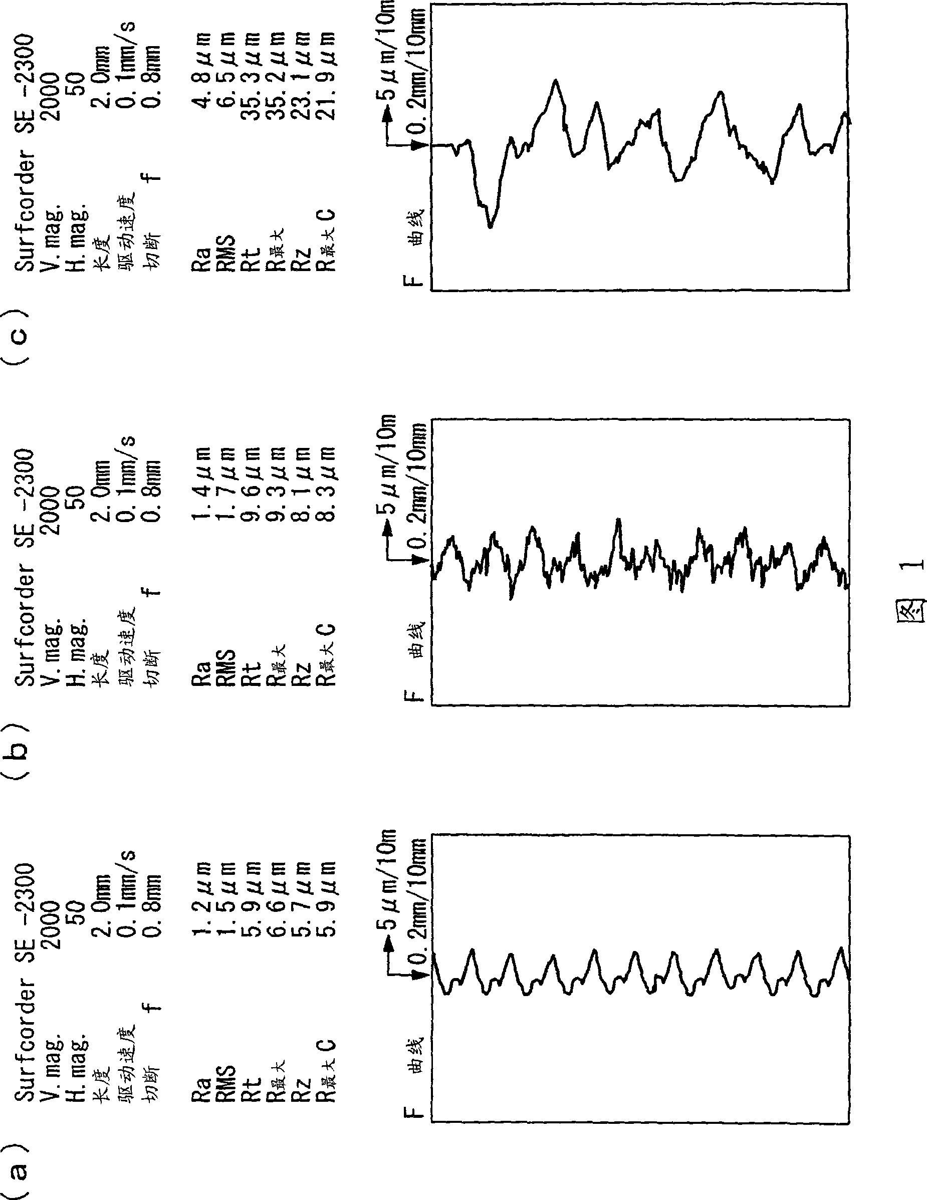
[0053] A plate-shaped aluminum alloy material (7050-T7451, size 19mm×76mm×2.4mm) is used as a test piece, and a projection material composed of alumina / silica ceramic particles with an average particle size (highest frequency diameter) of 50 μm or less is used. The injection pressure is 0.4MPa, and the projection time is 30 seconds, and the single surface is subjected to shot peening treatment.
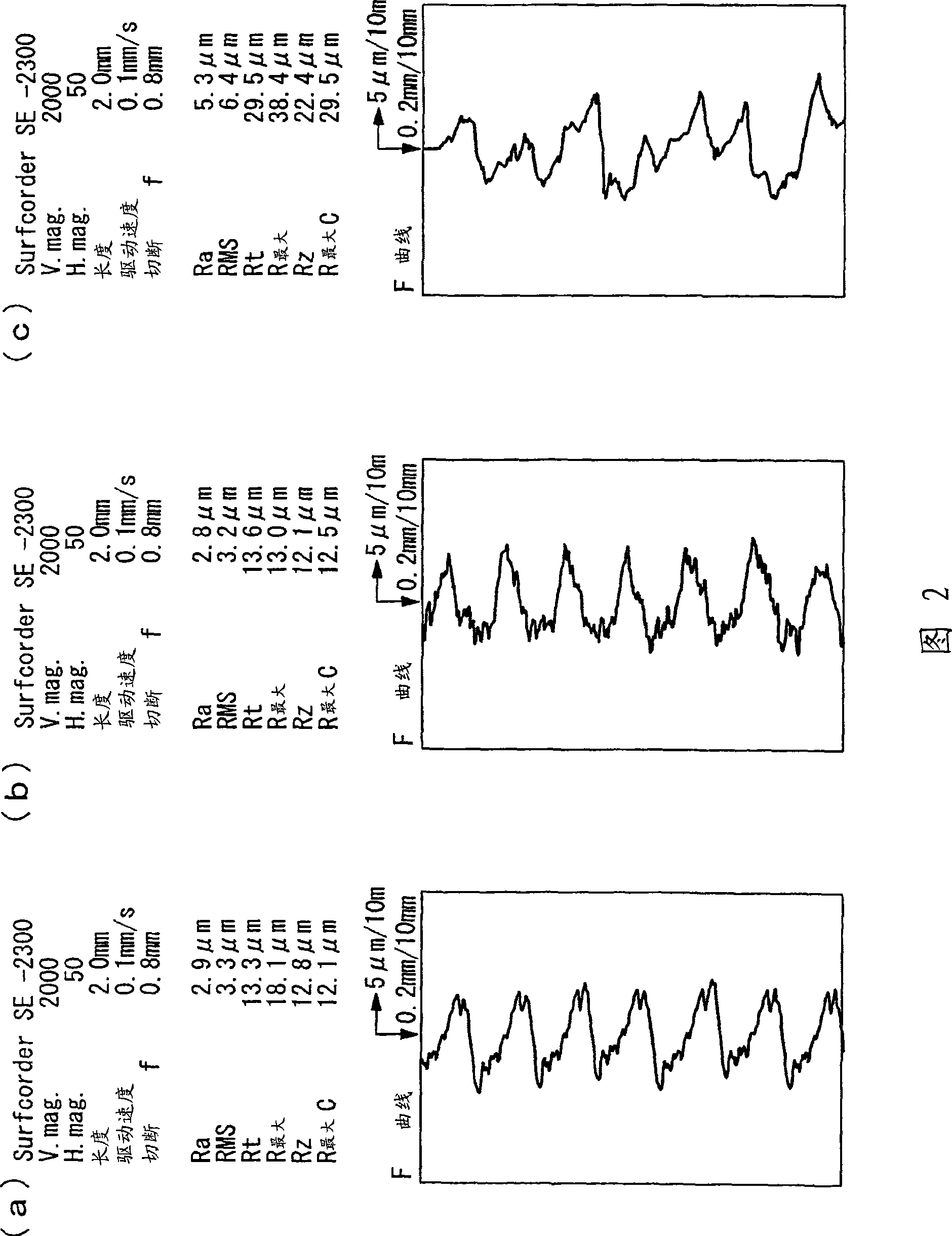
[0054] Two types of aluminum alloy materials having different surface roughness were prepared as the aluminum alloy material before the shot peening treatment. In Example 1, an aluminum alloy material with a surface roughness of 1.2 μm before shot peening was used, and in Example 2, an aluminum alloy material with a surface roughness before shot peening of 2.9 μm was used.
[0055] As the shot peening treatment device, a gravity type fine particle launcher (Pneumatic shot blasting machine manufactured by (Japan) Fuji Seisakusho Co., Ltd. - model P-SGF-4ATCM-401) was used.
[0056] Af...
Embodiment 3 and Embodiment 4
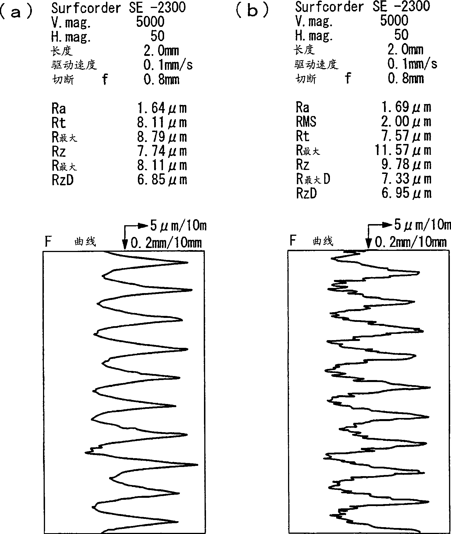
[0065] In addition to replacing the test piece with a plate-shaped titanium alloy material (Ti-6Al-4V (annealed material), size 19mm × 76mm × 2.4mm), then it is the same as embodiment 1 and embodiment 2, and carries out embodiment 3 and embodiment 4 shot peening treatment.
[0066] Two types of titanium alloy materials having different surface roughness were prepared as the titanium alloy material before the shot peening treatment. In Example 3, a titanium alloy material with a surface roughness of 1.64 μm before shot peening was used, and in Example 2, a titanium alloy material with a surface roughness before shot peening of 3.2 μm was used.
[0067] The shot peening treatment conditions of embodiment 3 and embodiment 4, the surface roughness of the test piece before and after the shot peening treatment, and the compressive residual stress, surface roughness, deformation and fatigue life after the shot peening treatment are shown in the table 1. The fatigue life was evaluat...
Embodiment 5
[0075] The same shot peening treatment as in Example 3 was performed on the hole portion of the test piece made of a titanium alloy (Ti-6Al-4V (annealed material)) perforated flat plate. No chamfering or rounding of the corners of the hole is performed before shot peening. After the fatigue test, the fatigue fracture surface was observed with an electron microscope. Figure 6 It is an electron micrograph of the fatigue cross-section of the test piece of Example 5. The arrows in the figure indicate the starting point of fatigue failure.
[0076] From Figure 6 It can be seen from the electron micrograph of Example 5 that there is a starting point of fatigue fracture from the inner surface of the hole of the test piece to the inside of about tens of μm.
[0077] Table 2 shows the results of a fatigue test (tensile-tensile fatigue test, stress ratio R=0.1) using the above-mentioned effective flat plate. It can be seen that it has nothing to do with the treatment of not implem...
PUM
| Property | Measurement | Unit |
|---|---|---|
| particle diameter | aaaaa | aaaaa |
| roughness | aaaaa | aaaaa |
| roughness | aaaaa | aaaaa |
Abstract
Description
Claims
Application Information