
Method and system for remote exhaust emission measurement

A detection system, remote sensing technology, applied in measuring devices, color/spectral characteristic measurement, material analysis through optical means, etc., can solve the problems of expensive trucks, restrictions, heavy cables, etc.

Active Publication Date: 2009-04-01
MUTUAL SKY TECH
View PDF9 Cites 18 Cited by
  • Summary
  • Abstract
  • Description
  • Claims
  • Application Information

AI Technical Summary

Problems solved by technology

In addition, this power supply system requires long, heavy cables to reach the remote sensing test location
some remote sensing systems mount this generator on a custom van which is very expensive and also requires extensive modifications to the van
The parking space of such trucks is also limited, as it is not always possible to park near the test location of the remote sensing system equipment

Method used


Image

  • Method and system for remote exhaust emission measurement
  • Method and system for remote exhaust emission measurement
  • Method and system for remote exhaust emission measurement

Examples


Embodiment Construction

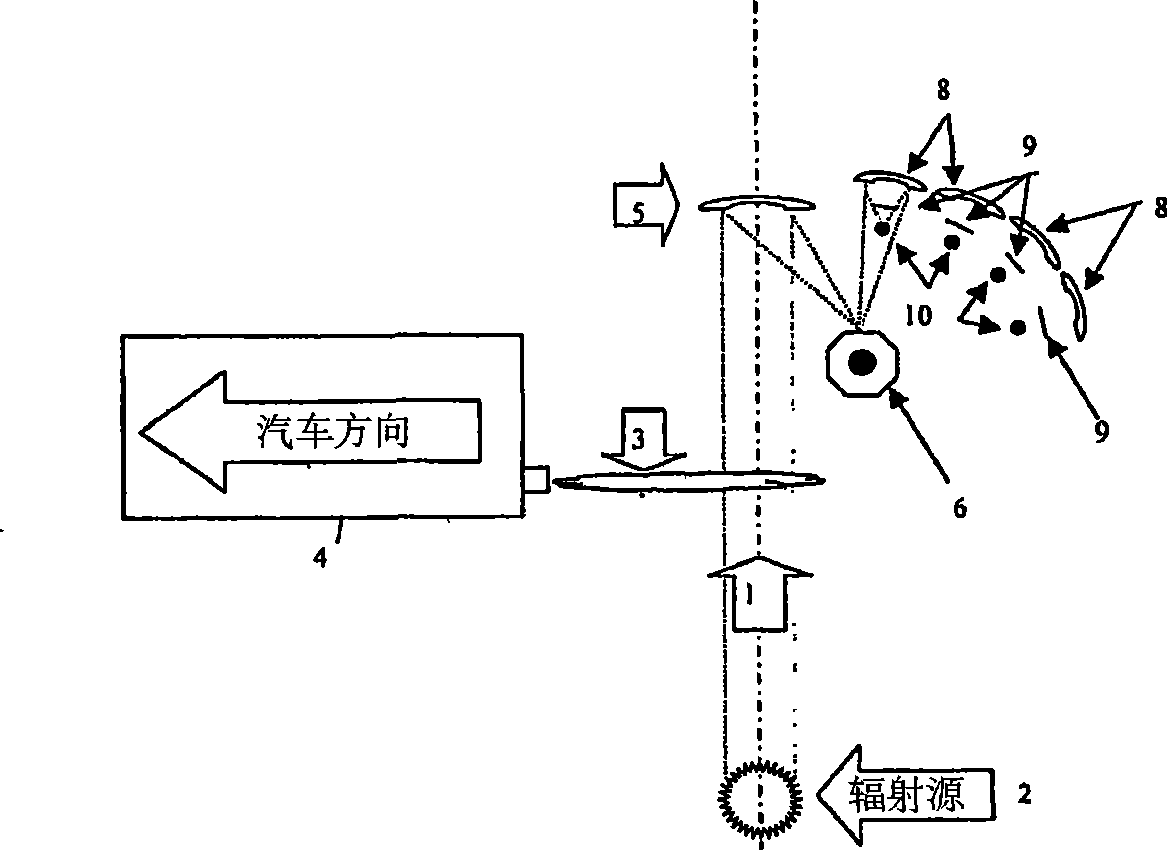
[0053] figure 1 The prior art vehicle emission remote sensing detection equipment is shown, in which a radiation source 2 emits a light beam 1 , the light beam 1 passes through the exhaust plume 3 of a vehicle 4 , and is reflected by a mirror 5 onto a reflective turntable 6 . The light beam 1 is reflected by the reflecting turntable 7 to one of the reflecting mirror groups 8 in turn; thus, it is focused by a respective filter 9 and reflected to a respective detector 10 .

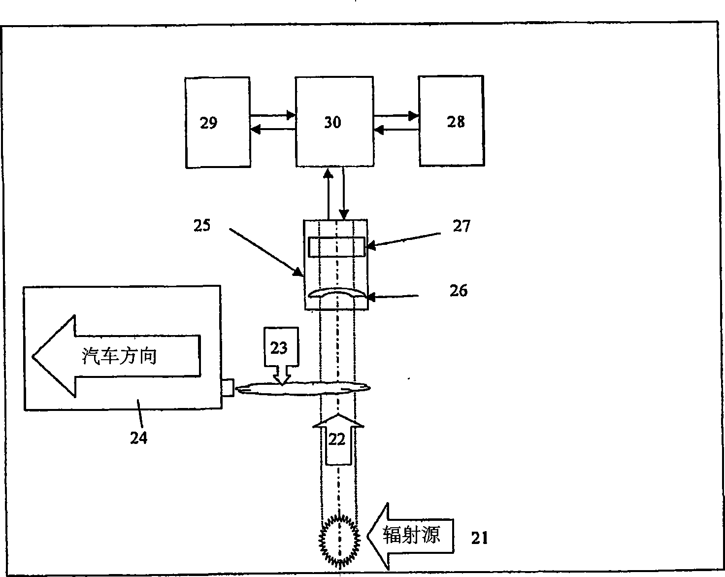
[0054] Such as figure 2 Shown is an embodiment of a vehicle emission remote sensing detection system according to the present invention, which can remotely determine the composition of vehicle exhaust and can be installed in many different locations, such as highway entrances or exit ramps. When required, it can be moved to a different location and installed in a new location to determine the same or different components of vehicle exhaust. It can also be permanently installed on the roadside, and the col...


PUM


Abstract

A remote vehicle emissions measurement system comprising a radiation source, an adaptable radiation detection unit and a processing unit, characterized in that the radiation source comprises an infrared source, an ultraviolet source or a combination thereof; the radiation detection unit comprises one or more detachable and expandable detecting elements for receiving the set of predetermined wavelength bands and producing a plurality of corresponding response concurrently at any one time instant; and the processing unit comprises one or more specific software and hardware for calculating the concentrations of various gas components thereof, the relative ratio of one gas component to the others, or the absolute emission values of each of the gas components thereof in an accurate and practicable manner.

Description

technical field [0001] The invention relates to tail gas remote sensing analysis, more specifically, to a tail gas remote sensing detection system and method. Background technique [0002] It is well known that remote sensing systems can detect and identify exhaust fumes emitted by vehicles, in which rotating devices such as reflective turrets or movable filters can be integrated so that one or more detectors can receive signals with different wavelength bandwidths passing through the exhaust plume. light beams so that the various gas components of the exhaust plume can be analyzed and monitored. [0003] US5,210,702 discloses such a remote sensing system, wherein a collimated beam emitted by a radiation source passes through the exhaust plume of a car, and is reflected by an adjustable mirror onto a reflective turntable therein. The beam is then reflected to a focusing mirror, and then passes through its own filter to several detectors in sequence. [0004] WO 00 / 42415 di...

Claims


Application Information

Patent Timeline
IPC IPC(8): G01N21/31
CPCG01N21/3504G01N21/31G01N21/33
Inventor 陆伟明
Owner MUTUAL SKY TECH
Learn More