
Carbon fiber surface modification method

A surface modification, carbon fiber technology, applied in the direction of carbon fiber, fiber treatment, textiles and papermaking, etc., can solve the problems of uncontrollable distribution and arrangement of functional groups on the surface of carbon fiber, unfavorable carbon fiber interface mechanism research, etc., to increase wettability And the two-phase interface adhesion, improving the interfacial shear strength, the effect of improving the interfacial shear strength

Inactive Publication Date: 2009-04-08
HARBIN INST OF TECH
View PDF0 Cites 38 Cited by
  • Summary
  • Abstract
  • Description
  • Claims
  • Application Information

AI Technical Summary

Problems solved by technology

[0003] In order to solve the problem that the distribution and arrangement of functional groups on the carbon fiber surface modified by the general carbon fiber surface treatment method are not controllable, which is not conducive to the study of the mechanism of the carbon fiber interface, the invention provides a carbon fiber surface modification method

Method used


Image

  • Carbon fiber surface modification method
  • Carbon fiber surface modification method
  • Carbon fiber surface modification method

Examples


specific Embodiment approach 1

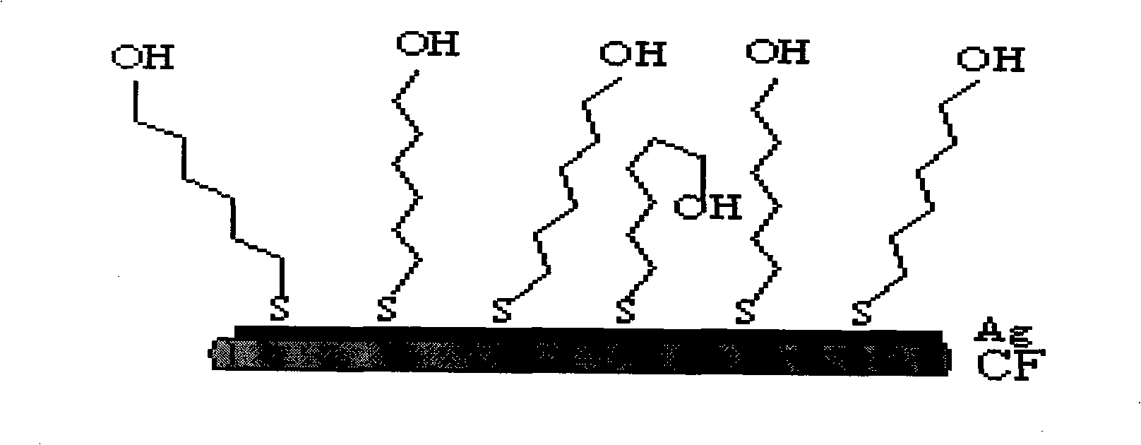
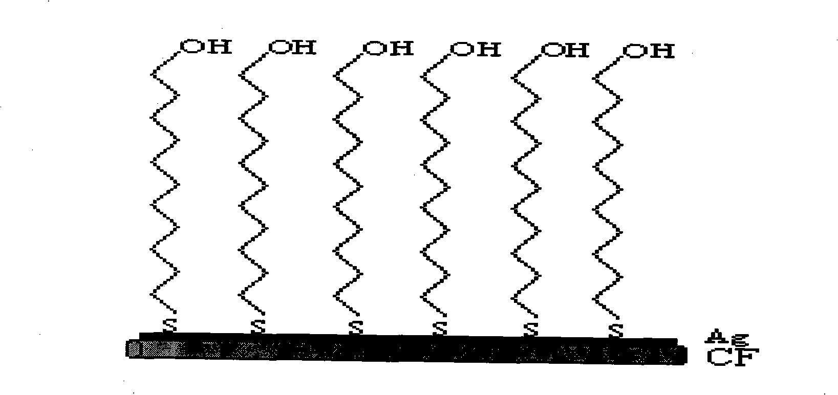
[0019] Embodiment 1: In this embodiment, the carbon fiber surface modification method includes two steps: 1. Electroless silver plating is performed on the carbon fiber surface; 2. Molecular self-assembly of organic sulfide is performed on the silver-plated carbon fiber.

specific Embodiment approach 2

[0020] Embodiment 2: This embodiment differs from Embodiment 1 in that the chemical silver plating process of carbon fibers includes two steps of material surface pretreatment and chemical silver plating. Others are the same as in the first embodiment.

specific Embodiment approach 3

[0021] Specific embodiment three: the difference between this embodiment and specific embodiment two is: the surface pretreatment of carbon fiber material is carried out according to the following steps: a, carbon fiber bundle is put into extraction device, extract 24h~96h under acetone boiling temperature , remove the carbon fiber surface coating; b. Under the condition of 30℃~80℃, immerse the decoated carbon fiber in the degreasing liquid and cook for 15min~60min for surface cleaning treatment; c. Put the surface cleaning treatment carbon fiber in HNO with a mass concentration of 25% to 40% 3 In the solution, soak for 5min to 20min at room temperature for roughening treatment; d. Neutralize the acid remaining in the depressions on the carbon fiber surface after roughening with NaOH solution with a mass concentration of 5% to 20%; e. Under the condition of ~40°C, put the neutralized carbon fiber into the sensitization solution with a pH of 0.6~2.0 and immerse it for 1.5min~10...


PUM


Abstract

The invention discloses a carbon fiber surface modification method, and relates to a carbon fiber modification method. The invention solves the problem of the uncontrollability of the distribution and arrangement of a carbon fiber surface functional group, which is not propitious to the study of the mechanism of a carbon fiber interface. The carbon fiber is plated with silver after surface pre-processing, then the carbon fiber with the silver-plated surface is infused in the dilute solution of thiol molecule containing sulfur element; depending on the coactions of the bonding reaction of sulfur atoms and metb and the force among self-assembly molecules, the thiol molecule has chemical absorption on the fiber surface and forms a closely arranged and ordered two-dimensional self-assembly single molecule membrane; two procedures are as follows: 1. the chemical plating of silver on the carbon fiber surface; and 2. the self assembly of molecules of organic sulfide on the silver-plating carbon fiber. The carbon fiber surface modification method has the advantages of realizing controllable, directional and ordered arrangement on the carbon fiber surface functional group from the molecule level, thus being beneficial to the study of the mechanism of the carbon fiber composite material interface.

Description

technical field [0001] The invention relates to a carbon fiber modification method. Background technique [0002] Carbon fiber reinforced composites are widely used in aerospace, automobile manufacturing and sporting goods because of their low density, high strength, high elastic modulus and superior corrosion resistance. However, due to the inert surface of carbon fiber, small specific surface area, low surface energy, lack of chemically active functional groups, poor wettability with resin and poor adhesion between two phase interfaces, it affects the performance of the entire composite material. In order to improve the interfacial properties of carbon fiber reinforced resin matrix composites, in recent years, various methods have been used for surface treatment of carbon fibers, such as: gas phase oxidation, liquid phase oxidation, electrochemical oxidation, electrodeposition, electropolymerization, chemical grafting, chemical vapor phase, etc. Deposition, ultrasonic for...

Claims


Application Information

Patent Timeline
IPC IPC(8): D06M11/83D06M13/252D06M13/335D06M13/352C08K9/00C08J5/06D06M101/40
Inventor 姜再兴贾近贺金梅刘丽黄玉东刘立洵
Owner HARBIN INST OF TECH
Learn More