Accurate measurement apparatus and method for workpiece surface appearance

A workpiece surface, precision measurement technology, applied in the direction of measuring devices, optical devices, instruments, etc., can solve the problems of limited measurement range, slow measurement speed, inability to overcome the wavelength drift of light source, etc., and achieve the effect of high measurement accuracy

Inactive Publication Date: 2009-04-08
HARBIN ENG UNIV
View PDF1 Cites 20 Cited by
  • Summary
  • Abstract
  • Description
  • Claims
  • Application Information

AI Technical Summary

Problems solved by technology

The disadvantages of this measurement method are: (1) Although the dual-channel or multi-channel measurement mode can be used, since the piezoelectric ceramic vibration direction and the measurement optical path are in the same direction, the measurement range of this method is limited, and it is only suitable for Single point measurement, slow measurement speed
(2) This method cannot overcome the drift of the wavelength of the light source. When the wavelength of the laser light source fluctuates, it will inevitably bring about systematic errors
(3) Compared with the two-dimensional CCD image sensing measurement method, the two-dimensional image cannot be directly measured, and the measurement range is very small in comparison
The disadvantages of this measurement method are: (1) The probe is used to realize the contact me

Method used


Image

  • Accurate measurement apparatus and method for workpiece surface appearance
  • Accurate measurement apparatus and method for workpiece surface appearance
  • Accurate measurement apparatus and method for workpiece surface appearance

Examples


Embodiment Construction

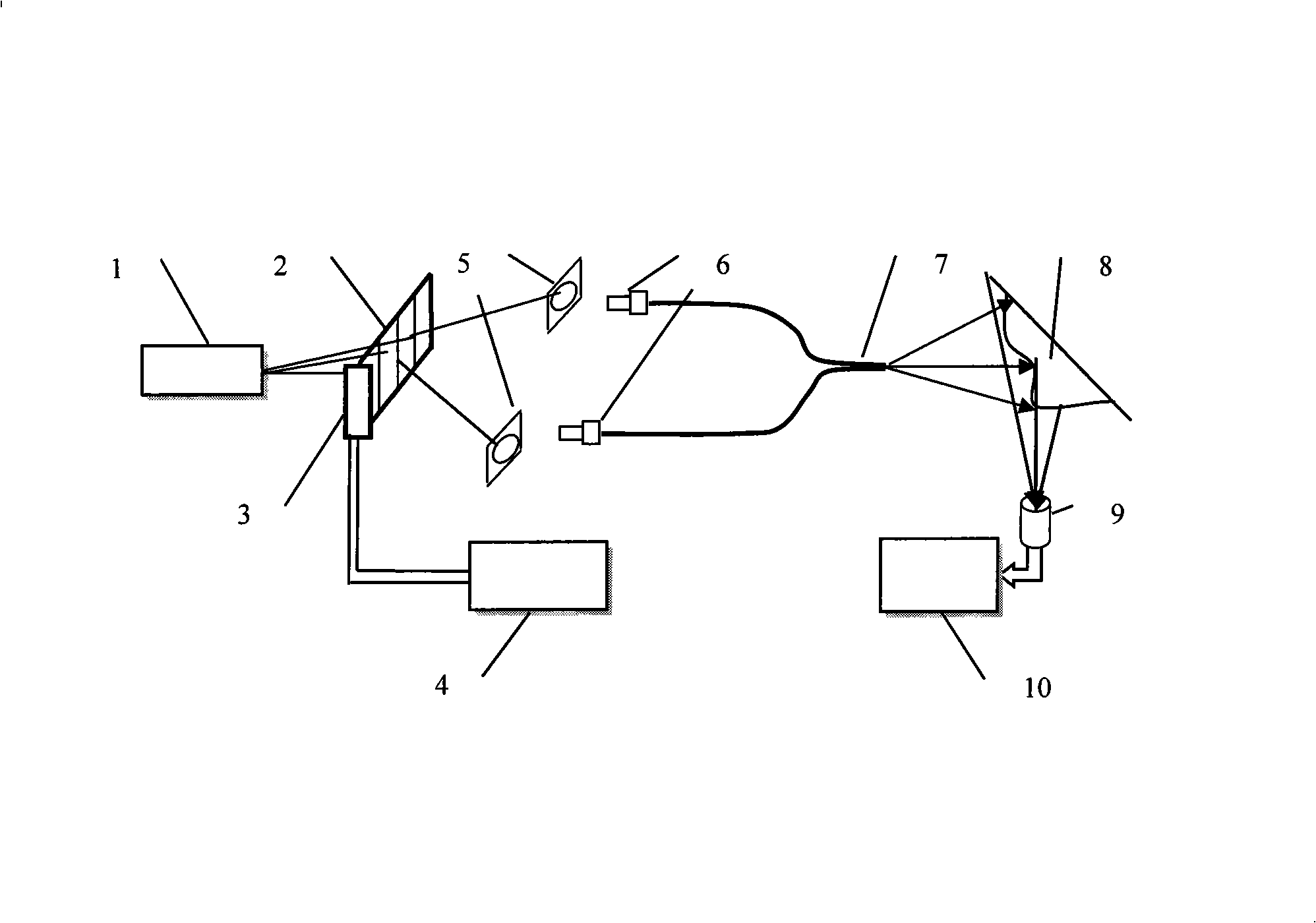
[0030] The present invention is described in more detail below in conjunction with accompanying drawing example:

[0031] In conjunction with the accompanying drawings, the composition of the workpiece surface topography precision measuring device of the present invention includes a laser 1, a grating 2, a piezoelectric ceramic 3, a signal generator 4, a focusing lens 5, an optical fiber connector 6, an optical fiber 7, a CCD detector 9 and The computer 10, the laser 1 is located in front of the grating 2, the piezoelectric ceramic 3 is installed on the side of the grating 2, the signal generator 4 is connected to the piezoelectric ceramic 3 through a wire, and the two focusing lenses 5 are located behind the grating 2, and the emitted light of the laser passes through the rear of the grating Generate multi-level diffracted light, and couple its ±1st-order diffraction spot into two optical fibers 7 through a focusing lens. The output end of the optical fiber 7 forms two coheren...


PUM


Abstract

The invention provides a precision measurement device and a measuring method based on workpiece surface appearance. Emergent light of a laser generates multi-level diffraction light after passing through a grating, the plus or minus 1 level diffraction facula is coupled into two fibers through a focus lens, two coherent point light sources are formed at the exit end of the fiber; the light beams emitted by two fiber point light sources have the same light intensity, therefore, a high contrast interference stripe is obtained and projected on the workpiece; when a piezoelectric ceramic drives the grating to carry out sinusoidal vibration, the position of the plus or minus 1 level diffraction facula coupled into two fibers is not changed, but the phase of the interference stripe generated by two fiber point light sources changes periodically; and the interference stripe image on the workpiece surface is acquired by a high-speed CCD image sensor, and the phase change of the interference stripe image is accurately measured by a sinusoidal phase algorithm. The invention overcomes influence to the object surface profile precision measurement by the light intensity and the wave motion of wavelength, and achieves the characteristics of the large measuring range, high precision and non-contact measurement.

Description

(1) Technical field [0001] The invention relates to an optical non-contact measuring device, in particular to a grating modulation optical fiber interference fringe phase type workpiece surface topography measuring device. The invention also relates to a measuring method using the measuring device. (2) Background technology [0002] Precision surface topography measurement technology is used to accurately measure the surface topography of various precision-processed objects. For example, optical device surfaces, precision cut surfaces, various ground and polished surfaces and other objects with small surface deformations. It can be divided into contact measurement and non-contact measurement. Non-contact measurement is mainly based on optical measurement. Traditional methods measure the continuous surface or stepped surface of the object profile, such as single-wavelength interferometry, dual-wavelength interferometry, fringe projection interferometry, Moore fringe method,...

Claims


Application Information

Patent Timeline
IPC IPC(8): G01B11/25
Inventor 戴强徐彦德
Owner HARBIN ENG UNIV
Why Eureka
Try Eureka