Elevator system and accumulator unit

A battery and discharge circuit technology, applied in electrical components, control systems, battery circuit devices, etc., can solve problems such as battery waste

Inactive Publication Date: 2009-04-15
HITACHI LTD +1
View PDF2 Cites 27 Cited by
  • Summary
  • Abstract
  • Description
  • Claims
  • Application Information

AI Technical Summary

Problems solved by technology

[0010] However, in order to supply the required power to the inverter and the drive control circuit, at least several batteries need to be connected in parallel, and if the battery with a higher voltage is used preferentially, it is necessary to prepare a relatively large number of batteries , and setting too many batteries will cause waste

Method used


Image

  • Elevator system and accumulator unit
  • Elevator system and accumulator unit
  • Elevator system and accumulator unit

Examples


Embodiment 1

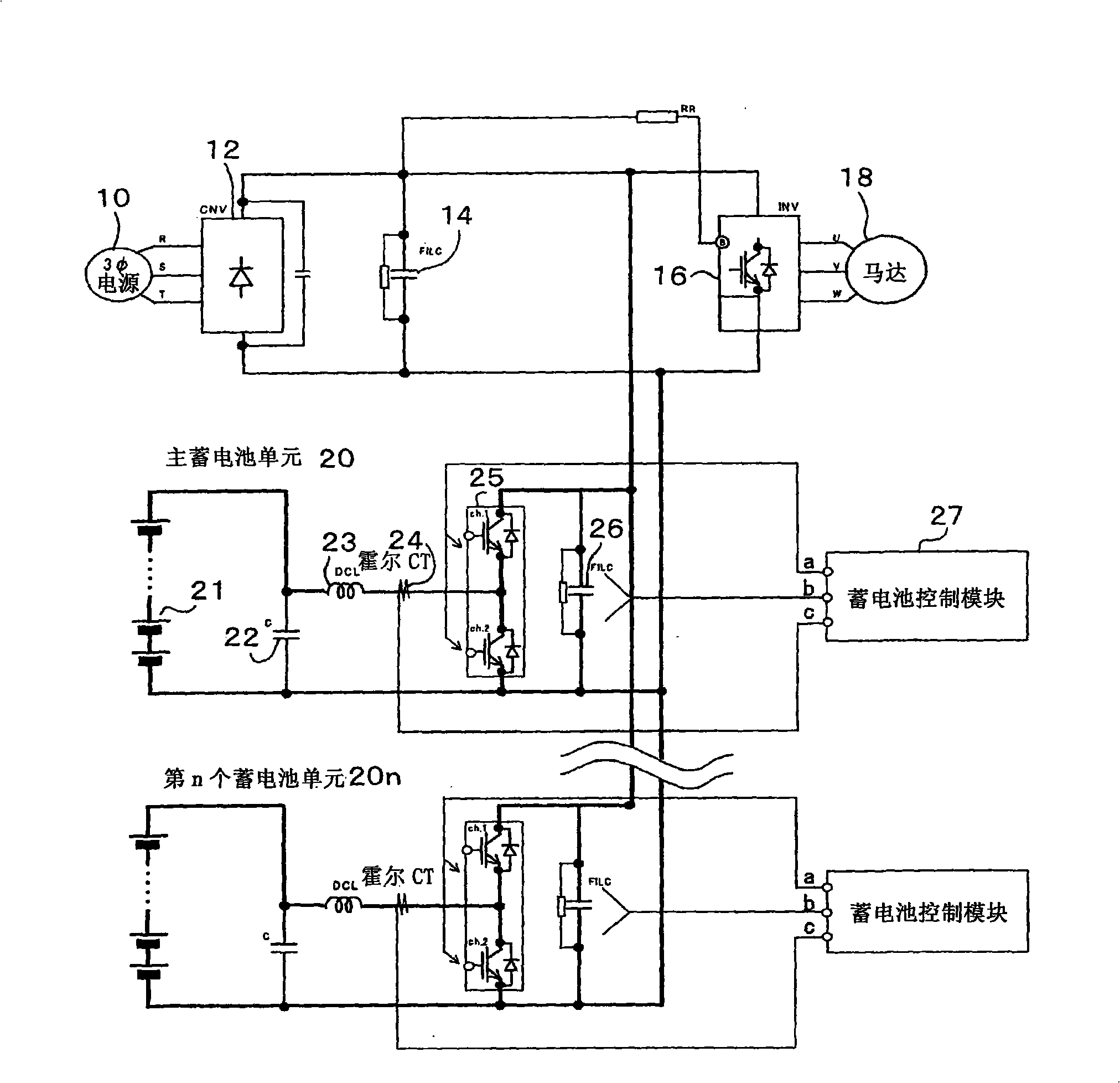
[0036] figure 1 It is a block diagram showing the system configuration of Embodiment 1 of an elevator system in which a plurality of storage battery units are connected in parallel according to the present invention.

[0037]The elevator system of Embodiment 1 has an inverter 12 that converts commercial AC power 10 into DC power, a smoothing capacitor 14, and an inverter that converts the DC power of the converter 12 into AC power with variable voltage and variable frequency and controls the elevator drive motor. inverter 16, and an unshown elevator control circuit that rectifies the commercial alternating current 10 and receives power to control the inverter 16. Among them, a plurality of storage battery units 20 connected in parallel and charged by the direct current of the converter 12 ˜20n have a storage battery charging / discharging circuit for charging the storage battery units 20˜20n when receiving the power supply of the AC power 10, and supplying DC power from the sto...

Embodiment 2

[0053] The elevator system of Embodiment 2 has an inverter 12 that converts commercial AC power 10 into DC power, a smoothing capacitor 14, and an inverter that converts the DC power of the converter 12 into AC power with variable voltage and variable frequency and controls an elevator drive motor 18. Inverter 16, and an unshown elevator control circuit that rectifies the commercial alternating current 10 and then receives power to control the inverter 16. Among them, a plurality of storage batteries connected in parallel and charged by the direct current of the converter 12 The units 20 to 20n have an elevator control circuit that charges the storage battery units 20 to 20n when receiving the power supply of the AC power 10, and charges the battery units 20 to 20n from the storage battery units 20 to 20n to the inverter 16 and the elevator control circuit (not shown) when the AC power 10 is cut off. The storage battery charging / discharging circuits 23-26 supplying direct curre...

Embodiment 3

[0057] The elevator system of Embodiment 3 has an inverter 12 that converts commercial AC power 10 into DC power, a smoothing capacitor 14, and an inverter that converts the DC power of the converter 12 into AC power with variable voltage and variable frequency and controls the elevator drive motor. inverter 16, and rectifies the commercial alternating current 10 and then receives power supply to control the inverter 16. An elevator control circuit not shown in the figure is further provided with multiple inverters connected in parallel and charged by the direct current of the converter 12. battery units 20-20n, the elevator control circuit has: battery charging / discharging circuits 23-26, which are respectively set corresponding to the battery units 20, and charge the battery units 20-20n when receiving the power supply of the alternating current 10, and When the AC power 10 is disconnected, DC power is supplied from the storage battery units 20 to 20n to the inverter 16 and t...


PUM


Abstract

The invention provides an elevator system which is provided with a device which can monitor the residual electric capacity of all batteries, correctly distributing the charging/discharging currents according to the quantity of batteries connected in parallel, and always sufficiently utilizes all batteries. The elevator system is provided with a plurality of battery cells which are charged by direct current of a converter, a battery discharging/charging circuit which charges the battery cell when the power is supplied by alternative current and a battery charging/discharging circuit which supplies direct current from the battery cell to an inverter and an elevator control circuit when the alternative current is turned off, and a battery control module which is provided with a device which can detect the quantity of parallel connected battery cells, a device which calculates the average charging current/upper limit discharging current of the battery cell according to the quantity of the detected battery cell, and a device which rectifies and arranges the charging/discharging current of all battery cells according to the discharged/charged quantity of all battery cells detected by the battery charging/discharging circuit and the average charging current/upper limit discharging current.

Description

technical field [0001] The present invention relates to an elevator system and a storage battery unit, and more particularly to a device for suppressing variation in charge and discharge between a plurality of storage battery units connected in parallel in a drive system including a drive motor such as a hybrid car or an elevator . Background technique [0002] In recent years, with the development of battery technology used in drive systems typified by hybrid vehicles, battery cells that have high energy density and can be quickly charged have been developed. [0003] For example, Patent Document 1 discloses an elevator system in which a plurality of storage battery units are connected in parallel in the DC part. box. [0004] In addition, for example, Patent Document 2 discloses an inexpensive and compact power supply device having means for canceling voltage variations of storage batteries connected in series. [0005] Patent Document 1: Japanese Patent Laying-Open No....

Claims


Application Information

Patent Timeline
Patent Type & Authority Applications(China)
IPC IPC(8): H02P27/06H02J7/00H02J9/06H01M10/44B66B1/06
CPCY02E60/12Y02E60/10
Inventor 杉山洋平三根俊介中田孝则保刈定夫鸟谷部润
Owner HITACHI LTD
Why Eureka
Try Eureka