Constant-pressure storage type high-pressure carbon dioxide extinguishing device with built-in evaporator

A high-pressure carbon dioxide and fire extinguishing device technology, which is applied in fire rescue and other fields, can solve the problems of low filling density, high initial pressure, and low initial pressure, and achieve the goal of improving refrigeration efficiency, reducing pressure bearing capacity, and improving reliability Effect

Inactive Publication Date: 2009-04-22
VITALONG FIRE SAFETY GRP
View PDF1 Cites 8 Cited by
  • Summary
  • Abstract
  • Description
  • Claims
  • Application Information

AI Technical Summary

Problems solved by technology

In my country, although the high and low pressure carbon dioxide fire extinguishing systems have been used for many years, because the fire extinguishing agent of the high pressure carbon dioxide fire extinguishing system is stored at room temperature, the filling density is low, so the storage equipment uses many steel cylinders, occupies a large area, and the cost is also low. High, the biggest advantage is that the initial pressure of spraying is high, up to 5.17MPa, the conveying distance of fire extinguishing agent is long, and ice blockage is not easy to occur when fire extinguishing agent is sprayed; for low-pressure carbon dioxide fire extinguishing system, due to the large loading coefficient, and The storage container stores the fire extinguishing agent, which occupies a small area and is relatively low in cost. The biggest problem is that the initial pressure of spraying is low, only 2.07MPa, and the transportation distance is short.
Chinese patent 200720078378.9 discloses a constant pressure storage type high-pressure carbon dioxide fire extinguishing device. Its evaporator assembly can be disassembled from the storage container. It is installed at the flange of the storage container manhole, and the evaporator structure is small , cannot be matched with a large refrigeration unit, so the cooling effect is not very good. In addition, when the air pressure of the fire extinguishing device does not reach the predetermined value, it cannot be adjusted manually

Method used


Image

  • Constant-pressure storage type high-pressure carbon dioxide extinguishing device with built-in evaporator
  • Constant-pressure storage type high-pressure carbon dioxide extinguishing device with built-in evaporator

Examples


Embodiment Construction

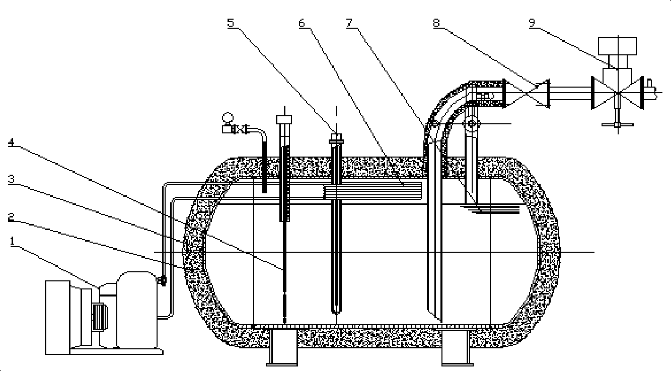
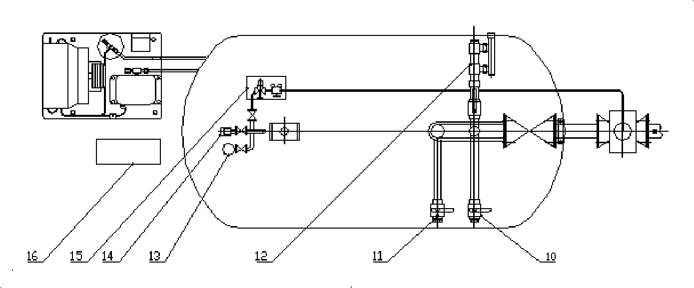
[0012] Below in conjunction with the accompanying drawings and specific implementation methods, the specific embodiments and working principles of the constant pressure storage type high-pressure carbon dioxide fire extinguishing device with a built-in evaporator of the present invention will be further explained and described in detail:

[0013] The structure of the constant-pressure storage type high-pressure carbon dioxide fire extinguishing device with built-in evaporator of the present invention is as follows: figure 1 , figure 2 Shown: Mainly composed of refrigeration unit 1, heat insulation layer 2, storage container 3, liquid level sensor 4, heating component 5, evaporator 6, fire extinguishing agent 7, inspection valve 8, master control valve 9, balance valve 10, filling valve 11. Safety pressure relief device 12, pressure gauge 13, pressure sensor 14, pneumatic control device 15, and controller 16. Wherein the evaporator 6 is located in the storage container 3 , an...


PUM


Abstract

The invention discloses a constant pressure storage type high-pressure carbon dioxide fire extinguishing device with a built-in evaporator, which comprises an evaporator (6), wherein the evaporator (6) is positioned in a storage container (3), and an inlet pipe and an outlet pipe of the evaporator (6) pass through the storage container (3) respectively and are connected with a refrigerating unit (1). The fire extinguishing device effectively solves the problems that a high pressure carbon dioxide fire extinguishing system has large occupied area and high manufacturing cost, and also effectively solves the problems that a fire extinguishing agent of a low pressure carbon dioxide fire extinguishing system has short conveying distance and is easy to generate ice blockage. At the same time, the fire extinguishing device has good refrigeration effect, and the pressure of carbon dioxide in the storage container can be maintained by adjusting the temperature of the carbon dioxide in the storage container.

Description

technical field [0001] The invention relates to a fire extinguishing device, in particular to a constant-pressure storage type high-pressure carbon dioxide fire extinguishing device with a built-in evaporator. Background technique [0002] Due to the destruction of haloalkane on the atmospheric ozone layer, the international community has made more and more strict restrictions on the use of haloalkane, and carbon dioxide is the preferred product to replace haloalkane. The carbon dioxide fire extinguishing system has been popularized and applied abroad for decades, and experienced a lot of fire tests. It is the earliest gas fire extinguishing system developed and applied. In my country, although the high and low pressure carbon dioxide fire extinguishing systems have been used for many years, because the fire extinguishing agent of the high pressure carbon dioxide fire extinguishing system is stored at room temperature, the filling density is low, so the storage equipment use...

Claims


Application Information

Patent Timeline
Patent Type & Authority Applications(China)
IPC IPC(8): A62C35/02
Inventor 汪映标
Owner VITALONG FIRE SAFETY GRP
Why Eureka
Try Eureka