
Plane target drone characteristic point automatic matching method for demarcating video camera

A camera calibration and planar target technology, which is applied in image analysis, image data processing, instruments, etc., can solve the problems of time-consuming, complicated target production, and the reduction of the number of feature points marked by ARTag in the recognition rate, so as to improve the degree of automation and calibration Efficiency, the effect of simplifying the calibration process

Inactive Publication Date: 2009-04-29
BEIHANG UNIV
View PDF0 Cites 18 Cited by
  • Summary
  • Abstract
  • Description
  • Claims
  • Application Information

AI Technical Summary

Problems solved by technology

The coordinate matching of the feature points of the planar target is a key link in the online on-site calibration of many cameras. In the actual online calibration process, the feature point matching is often a time-consuming task. It is usually done manually or semi-automatically, which directly affects the real-time calibration of the online calibration. and automation requirements
[0003] At present, the automatic matching methods of camera calibration target feature points are mainly divided into two categories, one is the matching method based on self-identifying targets, Mark Fiala in the article "Fully automatic camera calibration using self-identifying calibration targets" (Technical Report, NRC-48306 / ERB-1130, National Research Council, Canada, November 2005) using Mark Fiala's article "ARtag, a fiducial marker system using digital techniques" (IEEE Computer Society Conference on Computer Vision and Pattern Recognition, 2005, 2: 590~596) The ARTag two-dimensional code mark introduced in ARTag uses the center of the ARTag mark as the target feature point. According to the different black and white codes of the ARTag mark corresponding to different feature points, the automatic identification and matching of the feature points is realized. However, the target production of this method is complicated and the recognition rate The cost of improvement is the reduction in the number of feature points marked by ARTag
The other is an algorithm specifically for black and white checkerboard targets. In the article "Robust recognition of checkerboard pattern for camera calibration" (Optical Engineering, 2006, 45(9): 093201-1-9), Chunsheng Yu used the double triangle geometry structure on the checkerboard Make marks on the target, and realize the positioning of the four corners and the center of the target array through correlation operations, so that the rough position of the matching feature points can be obtained by using projective transformation, but this method cannot realize the feature points through correlation operations due to the noise and deformation of the captured image. Only when the target is completely photographed, the lens distortion is not large, and the image quality is relatively ideal can the initial coordinates of the matched feature points be obtained.
Chang Shu introduced the Delaunay triangulation method in the article "Automatic GridFinding in Calibration Patterns Using Delaunay triangulation" (Technical Report, NRC-46497 / ERB-1104, National Research Council, Canada, August, 2003), setting three A marker circle is used to provide the orientation information of the feature point search, and the gray feature of the black and white chessboard target is used to realize the quadrilateral meshing of the feature points, so as to realize the matching of the target feature points, but this method is specifically for the black and white checkerboard target, relying on three markers The orientation information provided by the circle and the grayscale features of the black and white chessboard target, otherwise the matching of feature points cannot be completed

Method used


Image

  • Plane target drone characteristic point automatic matching method for demarcating video camera
  • Plane target drone characteristic point automatic matching method for demarcating video camera
  • Plane target drone characteristic point automatic matching method for demarcating video camera

Examples


Embodiment

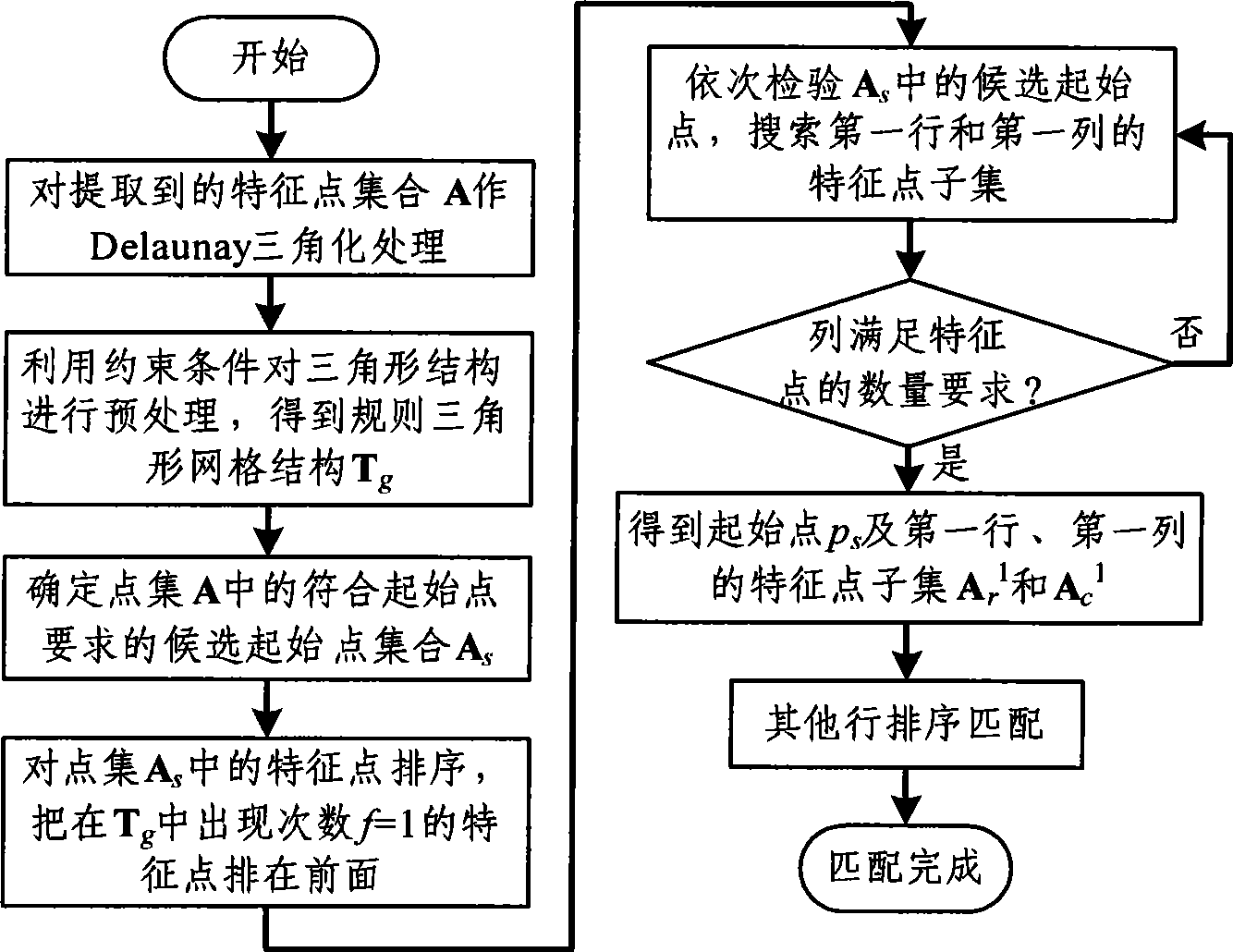
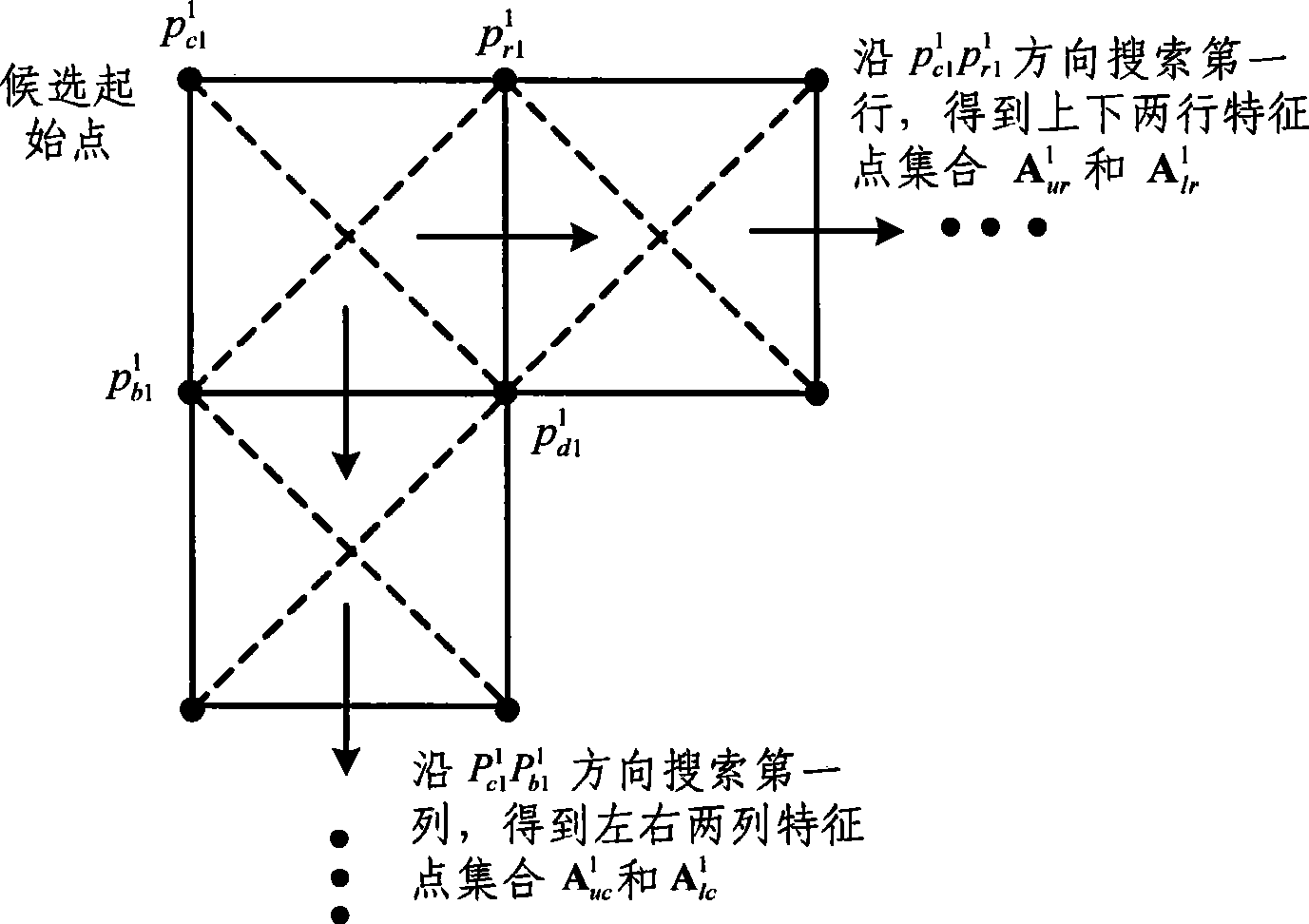
[0051] The process flow of the automatic matching method for the feature points of the plane target used for camera calibration proposed by the present invention is as follows: figure 1 As shown, the principle of using candidate starting points to search for feature points in the first row and feature points in the first column is as follows figure 2 shown.

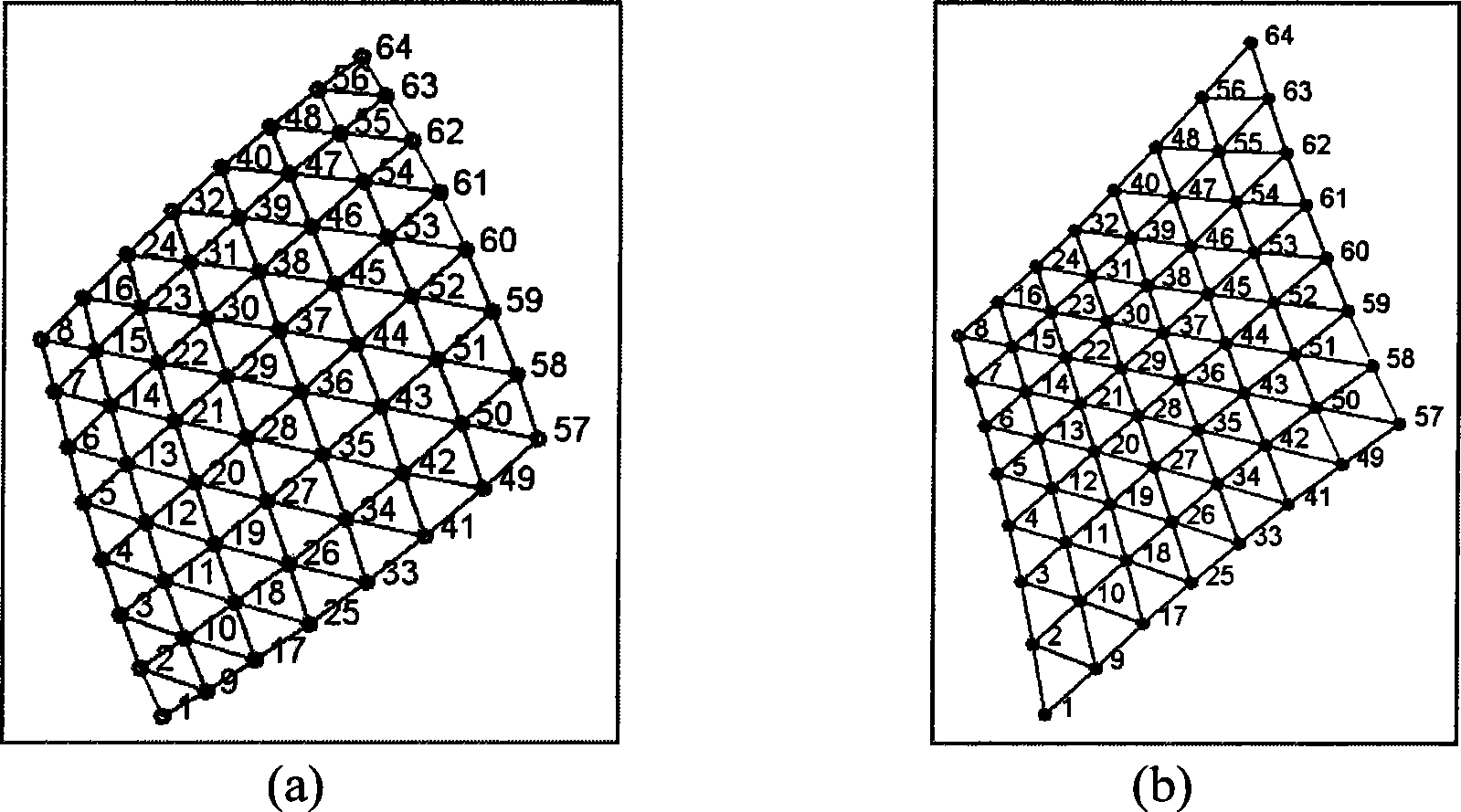
[0052] The feature points of the checkerboard target or circular target used for calibration generally have a grid array structure, so use a computer to generate 8×8 grid array feature points with a spacing of 20 mm, and the geometric center of all feature points is set to the world coordinate system origin. The simulation camera parameters are set as follows: the image resolution is 768pixel×576pixels, the effective focal length is f x = 500 pixels, f y =50 0pixels, principal point coordinate u 0 = 384 pixels, v 0 =288 pixels, the translation vector is (0, 0, 600) T , that is, the origin of the world coordinate sy...


PUM


Abstract

The invention belongs to the technical field of machine vision, and provides an automatic matching method of planar target characteristic points for camera calibration. The method comprises the following steps: performing Delaunay triangularization and necessary preprocessing in a computational geometry theory on the obtained calibration characteristic point set to obtain a geometrical connection relation between adjacent characteristic points; then searching the point set for an initial point, a characteristic point of a first line and a characteristic point of a first row which are used for determining the search direction; and finally, completing the matching of the rest lines according to the geometrical connection relation between the adjacent characteristic points, and realizing the matching between image coordinates of the planar target characteristic points in checkered array distribution and the world coordinates. The matching method of the characteristic points has simple realization and strong robustness, is insensitive to lens distortion, and is suitable for the matching of the characteristic points matching under the condition that the shooting inclination angle is large and the target is partially blocked, and is particularly suitable for online automatic calibration of cameras.

Description

technical field [0001] The invention belongs to the field of machine vision and relates to an automatic matching method for feature points of a plane target used for camera calibration. Background technique [0002] The main task of camera calibration is to solve the internal parameters and external parameters of the camera by knowing the two-dimensional image coordinates of the target feature points and the corresponding three-dimensional world coordinates. Camera calibration is an important part of computer vision, and has a wide range of applications in 3D vision measurement, robot vision navigation, reverse engineering and other fields. In camera calibration, there are mainly two types of targets, one is a three-dimensional target, and the other is a two-dimensional planar target. Due to the mutual occlusion between the different planes that constitute the three-dimensional target and the difficulty in processing high-precision three-dimensional targets, three-dimension...

Claims


Application Information

Patent Timeline
IPC IPC(8): G06T7/00
Inventor 周富强张伟张广军
Owner BEIHANG UNIV
Learn More