LED, production method therefore and illuminator manufactured by the LED

A technology of light-emitting diodes and illuminators, which is applied to the semiconductor devices of light-emitting elements, lighting devices, lighting and heating equipment, etc., can solve the problem that the side cannot emit effective light, the light transmittance is low, and the heat-conducting elements cannot properly emit high-power light. Diode chip heat and other issues

Inactive Publication Date: 2009-04-29
张守仁
View PDF0 Cites 24 Cited by
  • Summary
  • Abstract
  • Description
  • Claims
  • Application Information

AI Technical Summary

Problems solved by technology

[0010] However, since the structure of the aforementioned light-emitting diodes was designed to match the earlier low-power light-emitting diode chips, it is not suitable for use with high-power light-emitting diode chips.
When a high-power LED chip with a power greater than 0.5W or even as high as 1W is reluctantly used in the existing LED structure, it is not only impossible to properly dissipate the heat generated by the high-power LED chip when it is energized and illuminated by the aforementioned heat-conducting elements, the The weakness of the structure of the existing light-emitting diodes in terms of heat dissipation will lead to the inability to effectively improve the heat dissipation effect of high-power light-emitting diode chips by enlarging the heat-conducting elements
[0011] Due to the structure of the existing light-emitting diode, in order to match its production method, the body 81 of the base 80 is made of plastic material or resin material, and these materials have poor thermal conductivity and hinder heat conduction or heat dissipation, so the light-emitting diode chip 83 is produced. The heat is completely blocked by the body 81, so that the heat energy to be dissipated is continuously concentrated when the LED chip 83 is energized to emit light. In the case of a high-power chip emitting light, the concentrated heat can make the temperature reach a high temperature of 400 degrees Celsius; As a result, not only did the light-emitting diode chip 83 fail to operate properly due to heat, resulting in a serious decline in luminous effect, but the service life of the chip 83 was also greatly shortened, which not only had a negative impact on product quality, but also increased manufacturing costs and reduced market competition for products. In addition, high-power light-emitting diode chips are expensive, if they cannot fully exert their performance due to heat, it will increase the burden of manufacturing costs and cause unnecessary waste
However, within the acceptable range of existing equipment for producing light-emitting diodes, no matter how large the heat conduction element 813 is, because the material of the aforementioned body 81 is not conducive to heat dissipation, the heat dissipation effect it can provide cannot catch up with the heat production rate, so the traditional Existing light-emitting diodes that use plastic or resin materials as the body 81 of the base 80 cannot solve the problem of being heated
[0012] Furthermore, the body 81 made of the aforementioned plastic material or resin material not only has poor heat dissipation, but also has extremely low light transmittance. Therefore, the chip 83 installed in the housing space of the body 81 can only emit light toward the top surface, and its side cannot emit light. The effective light makes the lighting angle of the existing light-emitting diodes severely limited, so the existing light-emitting diodes only have top light and no side light, which is not suitable for general all-round lighting purposes, and their related applications are greatly restricted
[0013] In addition, since the existing equipment for producing light-emitting diodes mostly uses continuous stamping technology to manufacture the bracket (not shown in the figure), and then place the body 81 made of the aforementioned plastic material or resin material on the bracket as a surface. Adhesive design (surface mount design, SMD) technology forms the base 80, in order to cooperate with this production method, it is difficult to replace other materials at will
Moreover, the molds (not shown in the figure) used are not only expensive, but it is not only quite difficult to modify the structure of these molds, but also the cost of modification is also considerable, so it is difficult to make corresponding changes according to the outline of the order
For example, the aforementioned light-emitting diodes use two pins 82 to cooperate with one chip 83. If you want to change the combination of multiple low-power chips to make light-emitting diodes and need to change to a multi-pin structure, you must build a production line from scratch. is an unbearable cost burden
[0014] Also, it can be known from the foregoing that the existing LED illuminator is connected to the plate body 91 of the fixed plate 90 with the bottom end of its heat conduction element 813 to facilitate heat dissipation. In order to meet the operation needs of surface mount design (SMD), it is connected in a plane-to-plane way, and it is difficult to achieve a completely tight state, resulting in incomplete heat dissipation
[0015] From the above, it can be seen that the existing light-emitting diodes are limited by structure, materials and production methods, and it is difficult to use high-power light-emitting diode chips, which cannot effectively dissipate heat, have no side light, Limited by the production method, it is difficult to change the design, and the shortcomings of high cost and low efficiency need to be improved urgently

Method used


Image

  • LED, production method therefore and illuminator manufactured by the LED
  • LED, production method therefore and illuminator manufactured by the LED
  • LED, production method therefore and illuminator manufactured by the LED

Examples


Embodiment Construction

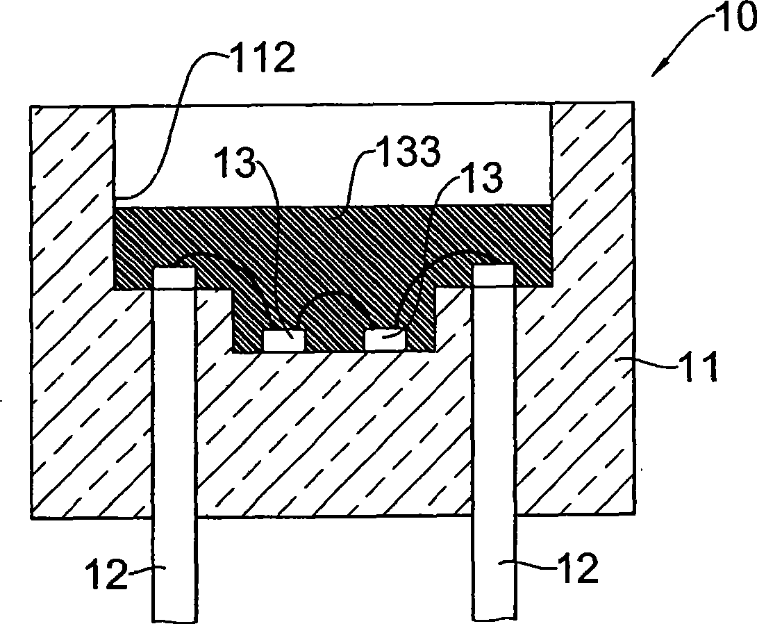
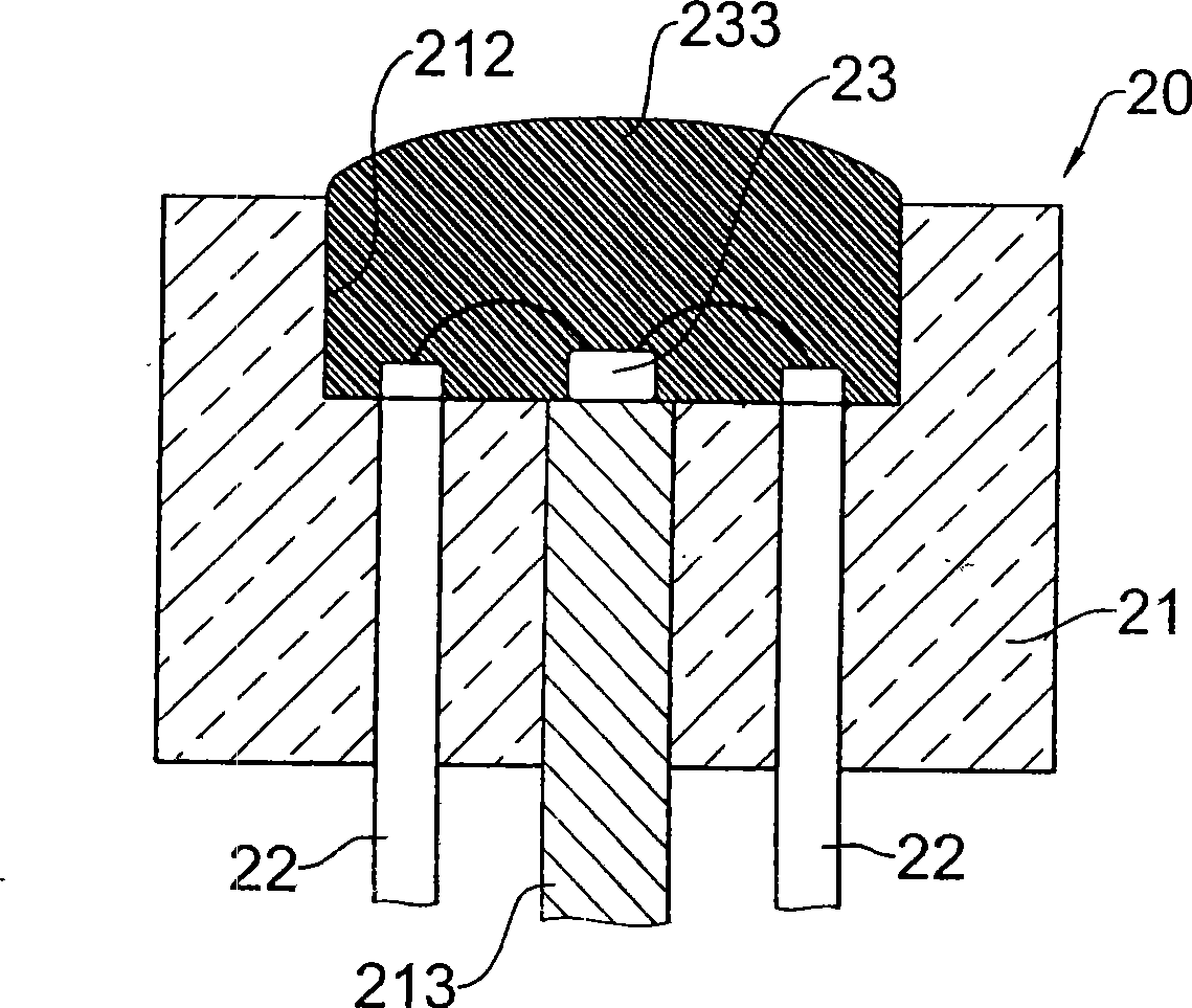
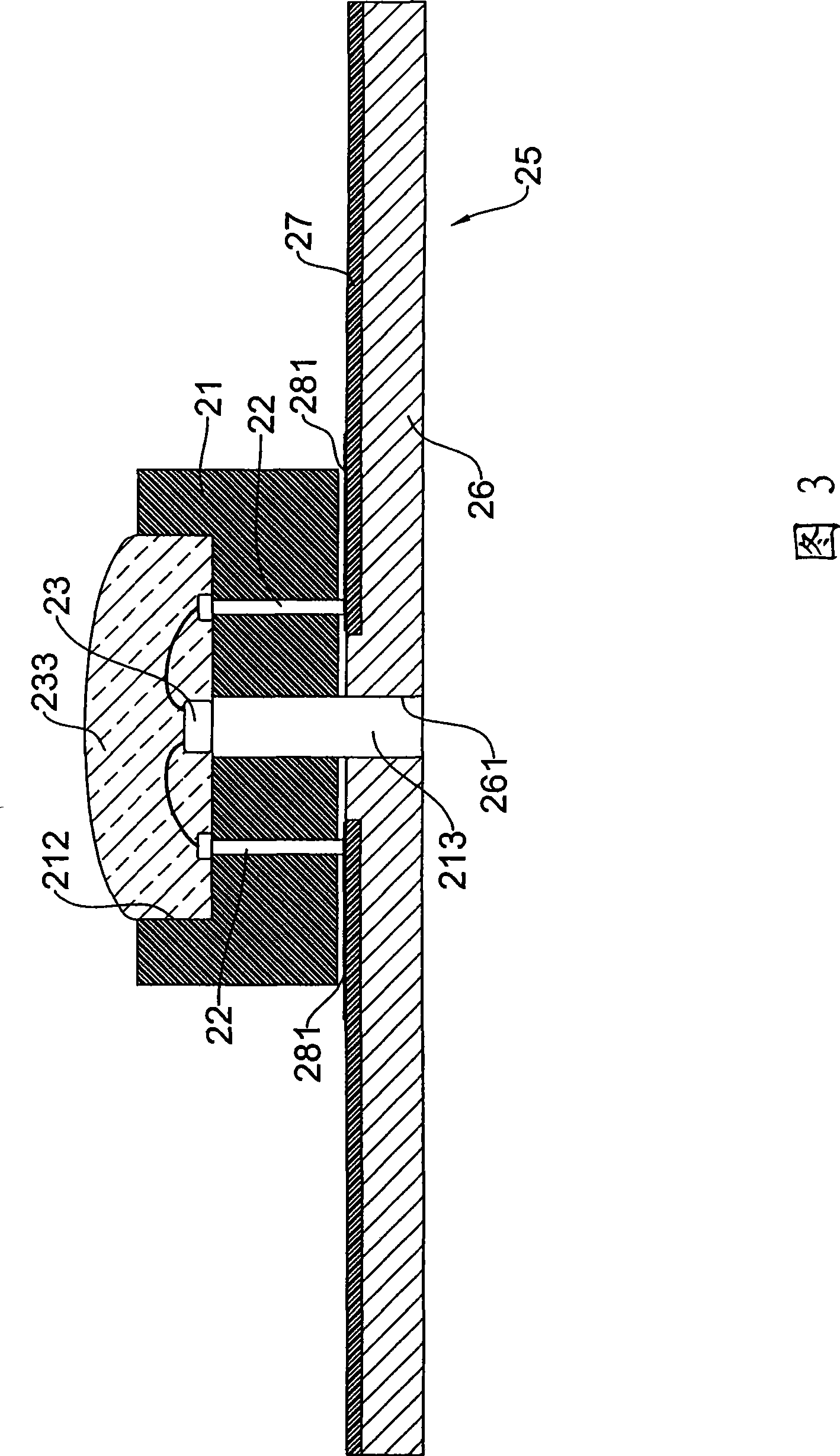
[0171] In order to further explain the technical means and effects of the present invention to achieve the intended purpose of the invention, the light-emitting diode proposed according to the present invention, its manufacturing method and the illuminator manufactured by the light-emitting diode are described below in conjunction with the accompanying drawings and preferred embodiments. Its specific implementation, structure, feature and effect thereof are described in detail as follows.

[0172] see figure 1 As shown, a side sectional view of a first embodiment of the present invention is disclosed.

[0173] The first embodiment of the present invention includes a base 10, which includes a body 11 made of a material with high thermal conductivity and high light transmission. The body 11 has a top surface and a back surface, and forms a container opening to the top surface Space 112 ; in this embodiment, the material with high thermal conductivity and high light transmissio...


PUM


Abstract

The invention relates to an LED, a manufacturing method thereof and an illuminator made from the LED. The LED mainly comprises a base which is provided with a body; the body is made from a material with high thermal conductivity and high light transmittance, and forms an accommodating space which opens towards the top surface; the body is internally buried with at least two connecting pins which are electrically connected with the outside, the accommodating space is internally provided with at least one LED wafer, and heat radiation can be properly achieved by the body with the high thermal conductivity and the high light transmittance; and the LED can be combined with a firmly arranged plate to form an LED illuminator. The invention further relates to the manufacturing method of the LED. The method comprises the following steps: providing materials, molding, semi-sintering, electroplating and combination, gas protection and complete sintering, electroplating, wafer fixing, routing, packaging colloid and the like to manufacture the LED. The LED can effectively dissipate heat, has ambient light, and is easy to change the design for evaluating the cost so as to have high efficiency.

Description

technical field [0001] The present invention relates to a light-emitting diode, in particular to a light-emitting diode using a base with high thermal conductivity and high light transmission; Method for making pedestal LED illuminator. Background technique [0002] Since the light-emitting diode (Light-emitting Diode, LED) chip has better energy application efficiency than traditional light bulbs or fluorescent lamps, and is smaller in size, it is more flexible in manufacturing and provides a wider range of applications. With the advent of diode chips, the market share of luminaires made of these light-emitting diode chips has been increasing year by year, and there is a tendency to replace traditional light bulbs or fluorescent lamp luminaires. [0003] see Figure 25 , which discloses an exploded perspective view of an existing light-emitting diode illuminator, which includes at least one light-emitting diode and a fixing plate, wherein: [0004] The LEDs include: [0...

Claims


Application Information

Patent Timeline
Patent Type & Authority Applications(China)
IPC IPC(8): H01L25/00H01L25/075H01L33/00H01L23/36H01L23/12H01L21/50F21V23/00F21V29/00F21Y101/02F21V29/50F21Y115/10
CPCH01L2224/48091H01L2924/3025
Inventor 张守仁
Owner 张守仁
Why Eureka
Try Eureka