Low melting point alloy thermal interface material

A technology of thermal interface material and heat dissipation module, which is applied in cooling/ventilation/heating transformation, electrical components, circuits, etc., and can solve problems such as leakage of hot melt droplets

Active Publication Date: 2009-04-29
IND TECH RES INST
View PDF3 Cites 22 Cited by
  • Summary
  • Abstract
  • Description
  • Claims
  • Application Information

AI Technical Summary

Problems solved by technology

Different use environments may make the effect of gravity more significant, for example Figure 1B As shown, some heat dissipation modules are installed vertically, that is, placed after turning 90 degrees (such as: the CPU heat dissipa

Method used


Image

  • Low melting point alloy thermal interface material
  • Low melting point alloy thermal interface material
  • Low melting point alloy thermal interface material

Examples


Embodiment Construction

[0035] The advantages and spirit of the present invention, as well as more detailed implementations, can be further understood through the following implementations and drawings.

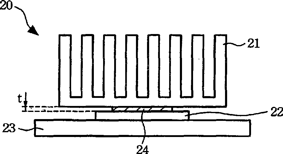
[0036] Please refer to Figure 2A , which is a schematic diagram of an embodiment of the heat dissipation module of the present invention. The heat dissipation module 20 of the present invention can quickly transfer the heat generated by an electronic component 22 to the external environment. The heat dissipation module 20 includes a heat sink 21 and a low melting point alloy foil 24 . As shown in the figure, the heat sink 21 is disposed above the electronic component 22 , and the low melting point alloy foil 24 is disposed between the electronic component 22 and the heat sink 21 , and serves as a thermal interface material between the electronic component 22 and the heat sink 21 . In addition, the electronic components 22 are disposed on a circuit board 23 and are electrically connected to each ot...


PUM

PropertyMeasurementUnit
Melting pointaaaaaaaaaa
Thicknessaaaaaaaaaa
Thicknessaaaaaaaaaa

Abstract

The invention relates to a low-melting-point alloy heat interface material which has low-heat impedance characteristic and can inhibit the spill of fusion liquid phase; the material is formed by necessary indium element and part or all elements such as bismuth, tin, zinc and the like, the fusion temperature is 55-85 DEG C, and the thickness of the material is not more than 0.04mm. A radiating module adopting the material comprises a radiator, a low-melting-point alloy chaff and a ring-shaped body. The radiating module can be applied in an electronic element, the radiator is arranged above the electronic element, the low-melting-point alloy chaff is arranged on the adjoining plane between the electronic device and the radiator and is used as the thermal interface material between the electronic device and the radiator, and the ring-shaped body is arranged between the electronic device and the radiator and surrounds the low-melting-point alloy chaff.

Description

technical field [0001] The invention relates to a low-melting-point alloy foil and a heat dissipation module using the low-melting-point alloy foil as a thermal interface material. Background technique [0002] Constructing microelectronic components, such as high-brightness light-emitting diodes and central processing units, etc., due to the development trend towards high power, high speed and / or miniaturization, the high heat flux generated by microelectronic components must be removed to maintain the junction temperature below its safe operating temperature. Once the junction temperature of the microelectronic element exceeds the safe operating temperature, the performance of the microelectronic element will be degraded, or the microelectronic element will be damaged, seriously affecting the service life and reliability of the electronic element. [0003] Along with the heat dissipation requirements of microelectronics and electronic components, the diversification and t...

Claims


Application Information

Patent Timeline
IPC IPC(8): H05K7/20H01L23/36H01L23/373C22C12/00C22C13/00C22C18/00C22C28/00C22C30/00
Inventor 范元昌陈俊沐苏健忠翁震灼黄振东萧复元林成全
Owner IND TECH RES INST
Why Eureka
Try Eureka