Dynamic state display apparatus of vehicle and display method

A technology for dynamic display and vehicle status, applied in signal devices, vehicle parts, bicycle accessories, etc., can solve problems such as conflicts, and achieve the effects of improving safety, rich colors, and a wide range of applications

Inactive Publication Date: 2009-05-13
龚立新
View PDF9 Cites 15 Cited by
  • Summary
  • Abstract
  • Description
  • Claims
  • Application Information

AI Technical Summary

Problems solved by technology

[0007] Another object of the present invention is to solve the problem of conflicts when displaying more than two

Method used


Image

  • Dynamic state display apparatus of vehicle and display method
  • Dynamic state display apparatus of vehicle and display method
  • Dynamic state display apparatus of vehicle and display method

Examples


Embodiment 1

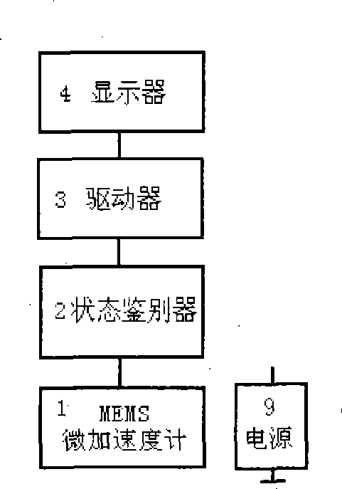
[0109] Embodiment 1: as figure 1 , figure 2 , Figure 4 ~ Figure 12 and Figure 14 As shown, this example is used for the LED display of the four states of sudden braking, rapid deceleration, general deceleration and acceleration; MEMS micro accelerometer 1 adopts ADXL05 of American Analog Devices Company, and is wired according to the range of ±2g, and the filter 5 is composed of C4 and R1 The high-pass filter removes the DC component and couples the signal of the alternating part to the output amplifier; 9 of ADXL05 is the output port, and different vehicle states generate different acceleration values ​​and output them to the vehicle state discriminator 2; the vehicle state discriminator 2 uses two Four-voltage comparison circuit LM339, the reference voltage generation circuit is composed of 5V power supply and R29, r4, R26, R25, r3, R21, R20, r2, R16, R14, r1, R11 resistors, adjustable potentiometer, r1 ~ r4 are The adjustable potentiometer is used to adjust the thres...

Embodiment 2

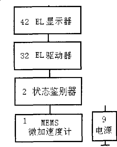
[0112] Embodiment 2: as figure 1 , Figure 3 ~ Figure 11 , Figure 13 , and shown in Figure 15, this example is to be used for the EL electroluminescent sheet display of four states of acceleration, rapid deceleration, slow braking and sudden braking; This example and the MEMS micro-accelerometer 1 of embodiment 1, the vehicle state discriminator 2. The filter 5 and the flash control circuit 8 are the same. The difference is that the display 4 uses an EL display, the driver 3 uses an EL driver, and the vehicle state discriminator 2 uses a positive pulse output. The vehicle state signal is divided into four by D3, D4, D5, and D6. output to the control bases of the four switching transistors A3, A4, A5, and A6. EL driver 31 adopts WD29EL driver circuit. WD29 can drive 600 square centimeters of EL electroluminescent film. There are four EL electroluminescent sheets EL1, EL2, EL3 and EL4 respectively corresponding to four colors or figures or characters.

[0113] The four ve...

Embodiment 3

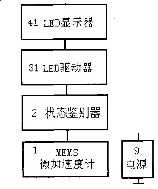
[0114] Embodiment 3: as figure 1 , figure 2 , Figure 4 ~ Figure 12 and Figure 16 As shown, this example is used to display four states of acceleration, sudden deceleration, slow braking and sudden braking; this example is the same as the driver 3 of embodiment 1, the difference is that the MEMS micro accelerometer 1 uses MMA1270EG, and the filter 5 is composed of R1, Composed of C2, used to minimize the clock noise, the display 4 uses three high-power LED dual-color light-emitting diodes; the vehicle state discriminator 2 uses two four-voltage comparator circuits LM2901 to form two voltage comparators and two window voltages Comparator, and all of them are negative pulse output, state holding / latch 6 is four monostable trigger circuits composed of two NE556 circuits, which store four vehicle state signals of acceleration, sudden deceleration, slow braking and sudden braking respectively The priority control circuit 7 adopts the direct reset port R (the 4th, 10 pins ) t...


PUM


Abstract

The invention relates to a vehicle dynamic display device and a displaying method thereof. The vehicle dynamic display device comprises an MEMS microaccelerometer, a vehicle state discriminator, a driver, a LED display or an EL emitting diode. An accelerometer is adopted for detecting state; an automatic decision can be performed on states of collision, emergency brake, urgency speed reduction, general speed reduction and acceleration through the vehicle state discriminator; real-time display can be respectively performed according to the urgent degree ordering in various colors, graphics, characters or the combination thereof; hand operation is replaced by automatic control, and the two signals of Preparation-Break replace break signals, so that the difficulty of Emergency Brake Precaution is solved. Once a vehicle is in danger, all vehicles thereafter can synchronously put on the brakes as well as the front vehicle, and an early warning time of 0.8 second to 1 second can be gained, thereby effectively avoiding the phenomena of driving too close to the car in front and serially driving too close to the car in front. The comprehensive early warning mechanism overcomes a plurality of defects in the traditional signal lamp and creates the beginning of mutual communication among vehicles, knowing one and others and safe driving. The invention has the advantages of low cost, high cost performance and simple installation, and is suitable for high-level installation at the tail parts of various vehicles and the installation of rear boxes of motorcycles and mopeds.

Description

(1) Technical field [0001] The invention relates to a device and a method for displaying changes in vehicle running speed, which belong to the field of vehicle lighting and signal devices in transportation. (2) Background technology [0002] With the construction of a large number of expressways and the improvement of automobile mobility, the speed and flow of automobiles have greatly increased, and traffic accidents have risen sharply. It is not uncommon for hundreds of cars to collide on expressways... . According to the survey report provided by the traffic accident research institute, traffic rear-end accidents account for 70% of the whole traffic accidents. There are many reasons for rear-end collisions. For example, modern cars running at high speed still use the outdated and backward light signal technology of the low-speed era in the 1940s. The vehicle signal device is a tool for vehicle "language" communication, and the "language" cannot be expressed clearly. The a...

Claims


Application Information

Patent Timeline
IPC IPC(8): B60Q1/00B60Q1/26B60Q1/44B62J6/00B62J6/04
Inventor 龚立新龚青王少磊刘麒麟翁琼华
Owner 龚立新
Why Eureka
Try Eureka