Radio communication device

A wireless communication device and antenna technology, which is applied in the direction of antenna support/installation device, middle position feed between antenna endpoints, resonant antenna, etc., can solve the problems of violating product miniaturization and low cost, and achieve simplified production and assembly , save cost, increase functional effect

Inactive Publication Date: 2009-05-13
DELTA ELECTRONICS INC
View PDF0 Cites 34 Cited by
  • Summary
  • Abstract
  • Description
  • Claims
  • Application Information

AI Technical Summary

Problems solved by technology

For the actual flex antenna 16, if the size of the flex antenna 16 itself is an area of ​​11.9 mm * 5 mm, an area of ​​14 mm * 6 mm must be reserved on the circuit board 10, therefore, still must Retain a certain area of ​​headroom, which violates the design concept of product miniaturization and low cost

Method used


Image

  • Radio communication device
  • Radio communication device
  • Radio communication device

Examples


Embodiment Construction

[0037] A wireless communication device according to a preferred embodiment of the present invention will be described below with reference to related drawings, wherein the same components will be described with the same component symbols.

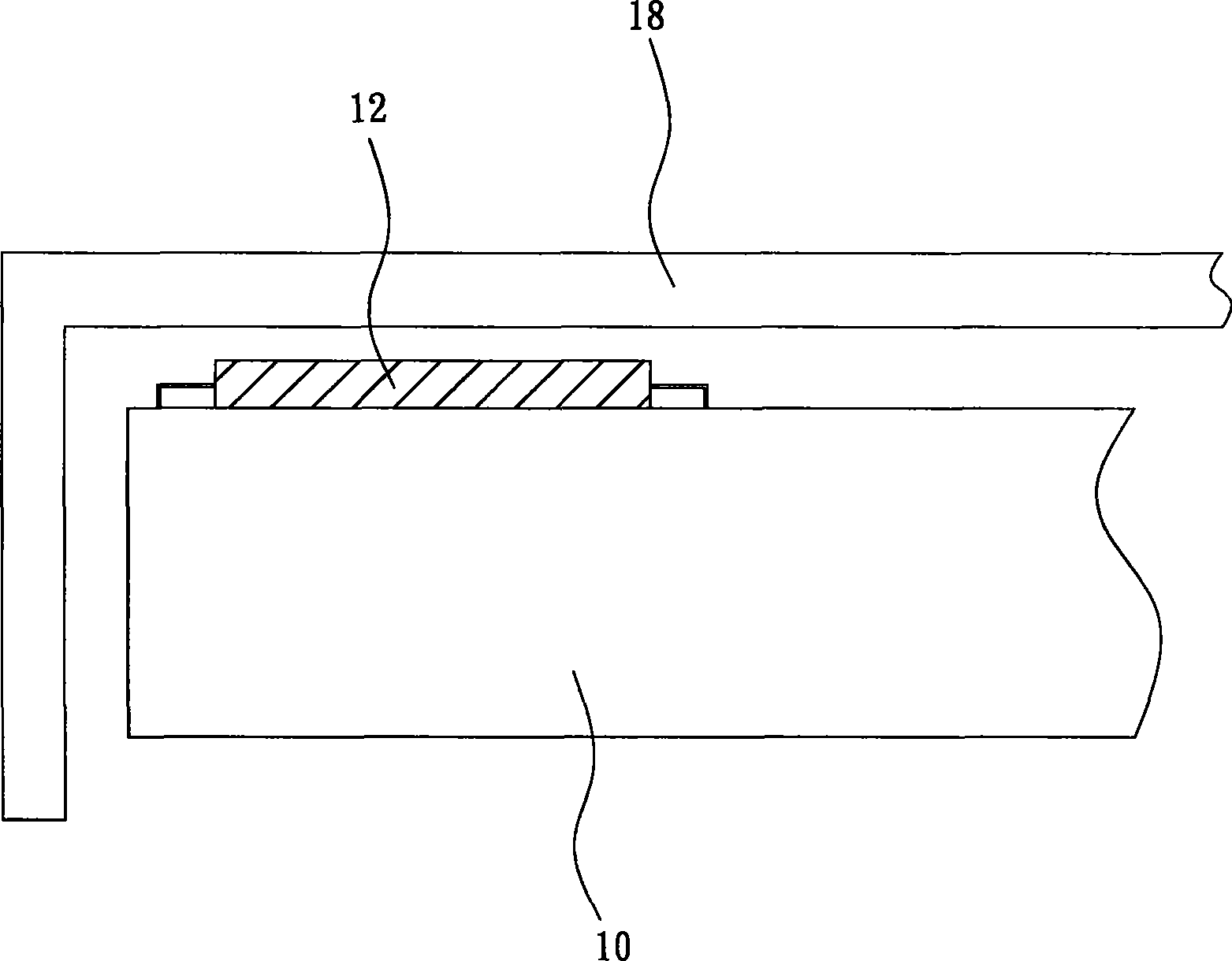
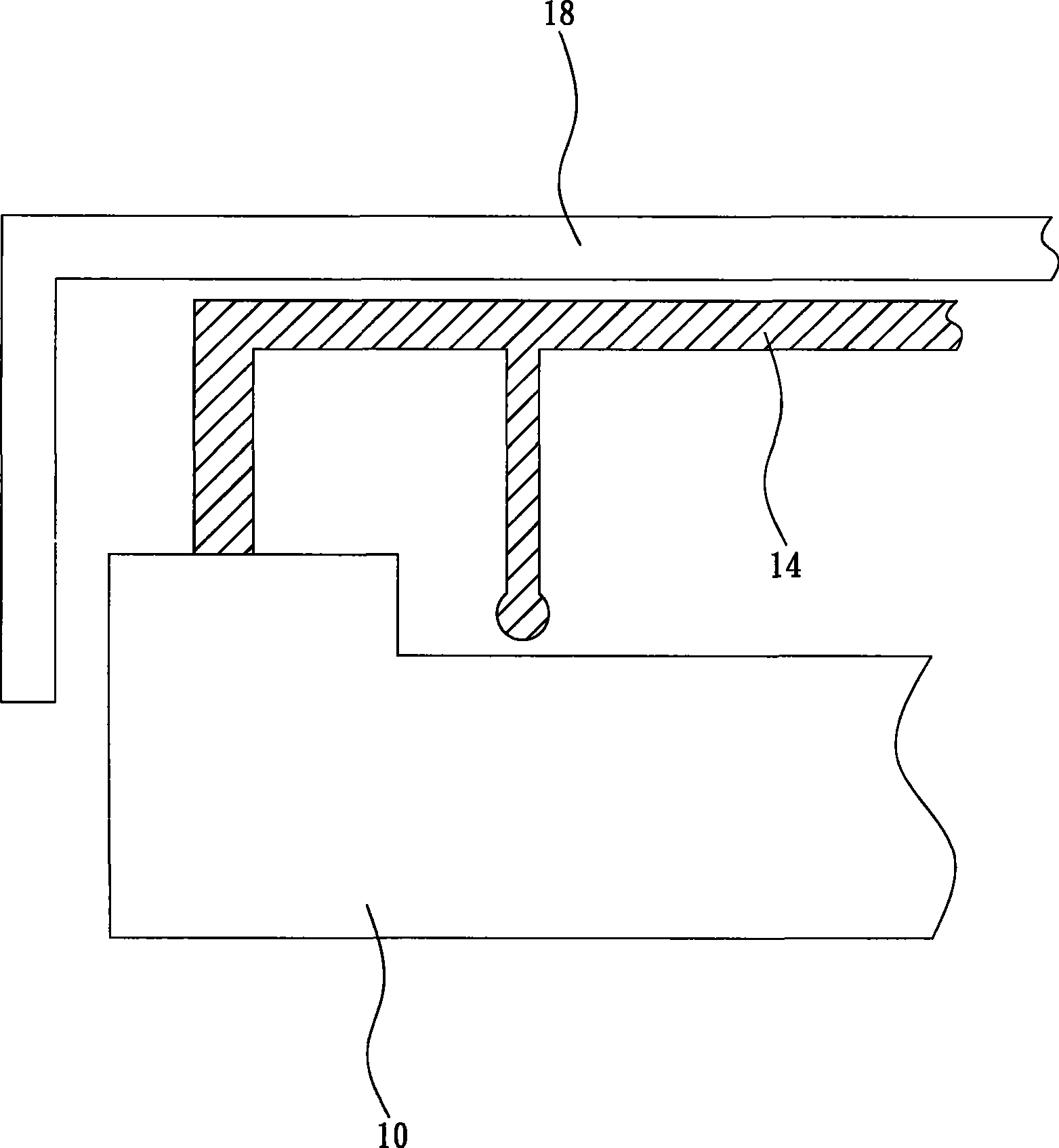
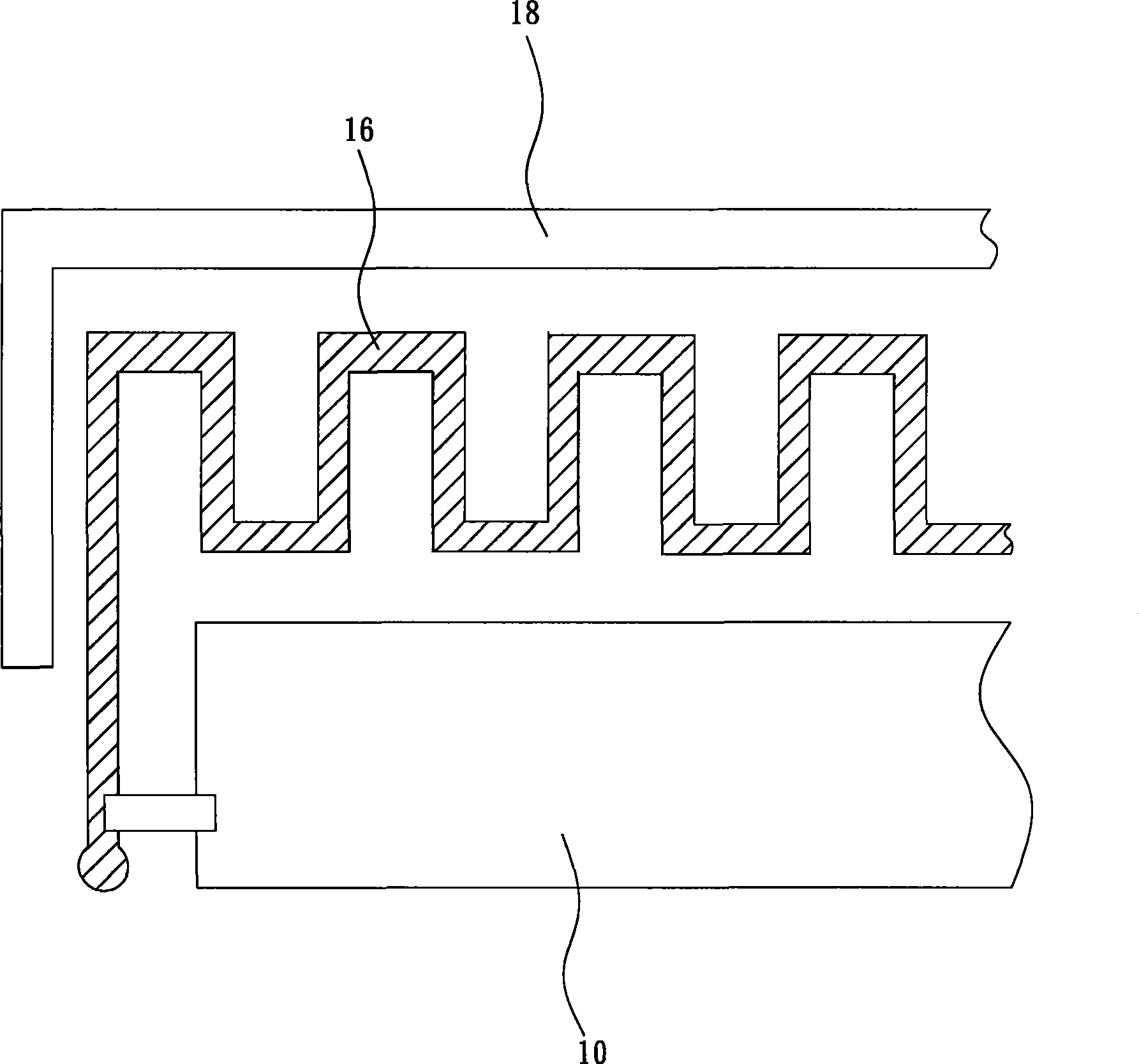
[0038] Please refer to figure 2 As shown in , it is a partial cross-sectional view of a preferred embodiment of the wireless communication device of the present invention. The wireless communication device includes a housing 20 , an antenna unit 22 and a protective layer 24 , and the antenna unit 22 is directly disposed on the outer surface 201 of the housing 20 .

[0039] The antenna unit 22 can be electrically connected to the feed-in point 261 on the circuit board 26 by means of wire connection or contact. The metal conductor 28 is used to electrically connect the antenna unit 22 to the feeding point 261 of the circuit board 26 ; wherein the metal conductor can be the above-mentioned wire. The protective layer 24 covers the antenna un...


PUM


Abstract

A wireless communication device comprises a shell body and an antenna unit. The antenna unit is arranged on the outer surface or the inner surface of the shell body, a protective layer can be selectively covered on the outer surface of the antenna unit, and the protective layer can cover part of the surface of the shell body. Therefore, the antenna which is not arranged on a circuit board can not only save the circuit layout area on the circuit board, but also use the saved layout area as other purposes, and the antenna unit is formed at the shell body, thereby enhancing the effectiveness of transceiving signals of the wireless communication device.

Description

technical field [0001] The invention relates to a wireless communication device, in particular to a wireless communication device with a metal paint antenna. Background technique [0002] Wireless communication electronic products are constantly improving and their types are becoming more and more diverse. For more beautiful and lighter designs, portable wireless communication devices, such as Bluetooth wireless headsets, low-power Zigbee, and wireless networks that can transmit large amounts of data The antenna design and configuration of (WiFi) and other products are under the trend of miniaturization, which directly affects the performance of the product. [0003] Please refer to Figure 1A As shown, it is a partial schematic diagram of a known wireless communication electronic product with an antenna arranged on a circuit board. The antenna 12 is formed directly on the circuit board 10 by coating, electroplating, evaporation or sputtering, and the housing 18 of the wire...

Claims


Application Information

Patent Timeline
Patent Type & Authority Applications(China)
IPC IPC(8): H01Q1/22H01Q1/38H01Q1/40H01Q9/16
Inventor 郑美兰
Owner DELTA ELECTRONICS INC
Why Eureka
Try Eureka