Trackless type self-protecting complete position automatic soldering device and welding process thereof

An automatic welding and self-protection technology, applied in welding equipment, manufacturing tools, arc welding equipment, etc., can solve the problems of many auxiliary welding materials, cumbersome equipment such as root welding machines, and high welding joint assembly accuracy, so as to ensure the welding joints. The quality and line energy are easy to control, and the effect of saving labor costs

Active Publication Date: 2009-05-20
SINOHYRDO ENG BUREAU 3 CO LTD +2
View PDF0 Cites 13 Cited by
  • Summary
  • Abstract
  • Description
  • Claims
  • Application Information

AI Technical Summary

Problems solved by technology

[0002] The existing automatic welding devices for large-diameter pipes and spherical tanks have the following defects and deficiencies: 1. Regardless of the magnetic seat suction cup or the negative pressure suction cup welding device, it is inseparable from the rail during the welding process, and the rail installation in the actual operation process It is very inconvenient, labor-intensive and time-consuming, and affects on-site welding operations; in addition, when using rails as guides, high welding joint assembly accuracy is required, which is difficult to achieve in the pairing of large-diameter pipes and spherical tanks, that is, storage tanks. Ultimately, the popularization and use of the above-mentioned welding device has been greatly restricted.
2. The existing automatic welding devices generally stop the wire feeding automatically after the welding is stopped, that is, when there is no welding current. to process
3. Most of the existing automatic welding devices use gas-shielded welding or double-shielded welding when welding, so the welding process needs to use a large amount of auxiliary welding materials such as CO2, Ar gas, etc., which is relatively not strong enough for wind resistance, especially in In remote areas, it is very difficult to purchase and transport gas, so the scope of use of the above welding devices is greatly limited
[0004] In summary, the above-mentioned automatic welding method has one or more of the following deficiencies and / or limitations of use conditions: ① only suitable for welding of pipes with small diameters; ② only suitable for welding of workpieces that can be rolled; Manufactured by the factory; ④Auxiliary welding materials used (CO 2 , Ar gas, etc.), the procurement management in remote areas in the field is inconvenient; ⑤ root welding machines and other equipment are cumbersome; And it is not suitable for the welding of curved seams; ⑦The track needs to be laid before welding, the process is complicated, the efficiency is relatively low, and the cost is high

Method used


Image

  • Trackless type self-protecting complete position automatic soldering device and welding process thereof
  • Trackless type self-protecting complete position automatic soldering device and welding process thereof
  • Trackless type self-protecting complete position automatic soldering device and welding process thereof

Examples


Embodiment 1

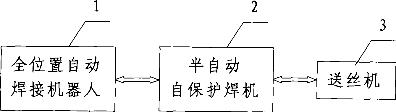
[0036] Such as figure 1 As shown, the trackless self-protection all-position automatic welding device used in the present invention includes an all-position automatic welding robot 1, a semi-automatic self-protection welding machine 2 driven by the all-position automatic welding robot 1 for welding, and a semi-automatic self-protection welding machine 2 connected The wire feeder 3. Wherein, the all-position automatic welding robot 1 includes a control system, a photoelectric tracking device connected to the control system and its feedback device, a walking trolley controlled by the control system, and a drive for driving the walking trolley. mechanism and the magnetic attraction device that adheres and fixes the walking trolley on the channel it moves, and the welding torch of the semi-automatic self-shielded welding machine 2 is fixed on the walking trolley of the all-position automatic welding robot 1 . The wire feeder 3 is internally provided with a time-delay arc breaking...

Embodiment 2

[0053] combine Figure 4 , in this embodiment, the material of the welded part 4 described in step 1 is SUMITEN610-TMC steel, and the self-shielded welding wire described in step 3 is a diameter 2.0mm self shielded welding wire JC-30 or diameter 5 / 64″mm self-shielded welding wire E71T8-K6.

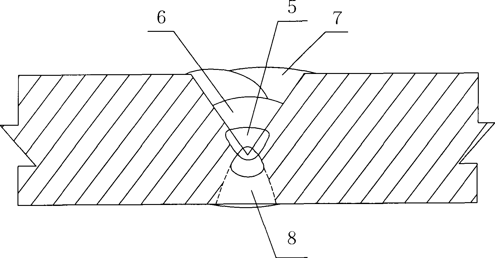
[0054] First of all, according to the conventional mechanical processing technology, the groove is processed on the welded part 4. The material of the welded part 4 is SUMITEN610-TMC controlled rolling steel, and the welded part 4 is a large-diameter pipe with a pipe wall thickness of 50 mm and a pipe diameter of 4000 mm. The groove is an asymmetric double-sided V-shaped groove, the depth of the outer groove is 6mm, and the rest of the depth is all inner grooves. Groove angle is 60 0 , the blunt edge at the groove is 0-2 mm, and the gap between the grooves is 0-2 mm. Place the large-diameter pipe joint horizontally (the pipe axis is parallel to the ground), and perform all-position w...


PUM

PropertyMeasurementUnit
lengthaaaaaaaaaa
diameteraaaaaaaaaa
thicknessaaaaaaaaaa

Abstract

The invention discloses a trackless self-protecting full-position automatic welding device and a welding process thereof. The device comprises a full-position automatic welding robot, a semiautomatic self-protecting welding machine driven by the full-position automatic welding robot to weld, and a wire feeding machine. The welding process comprises the following steps: sticking a guiding line for photoelectric tracking and guiding at an edge of a welding joint; scanning size of a welded junction section of the welding joint and relative positions of the welded junction section and the guiding line through a photoelectric tracking device, and carrying out automatic blurry memory; inputting welding technological parameters into a control system according to scanning results, or automatically selecting the welding technological parameters by the control system, and carrying out the automatic blurry memory; controlling a running trolley to run along the guiding line by the control system, and performing welding by a welding gun of the semiautomatic self-protecting welding machine fixed on the running trolley. The welding device has the advantages of reasonable structure and simple and convenient operation, can also improve welding efficiency at the same time of ensuring obtaining good welding joint, reduces labor intensity, and saves engineering cost.

Description

technical field [0001] The invention relates to an automatic welding device and its welding process, in particular to a trackless self-protection all-position automatic welding device and its welding process. Background technique [0002] The existing automatic welding devices for large-diameter pipes and spherical tanks have the following defects and deficiencies: 1. Regardless of the magnetic seat suction cup or the negative pressure suction cup welding device, it is inseparable from the rail during the welding process, and the rail installation in the actual operation process It is very inconvenient, labor-intensive and time-consuming, and affects on-site welding operations; in addition, when using rails as guides, high welding joint assembly accuracy is required, which is difficult to achieve in the pairing of large-diameter pipes and spherical tanks, that is, storage tanks. Ultimately, the popularization and use of the above-mentioned welding device is greatly restricte...

Claims


Application Information

Patent Timeline
Patent Type & Authority Applications(China)
IPC IPC(8): B23K9/16B23K9/12B23K9/133B23K9/10B23K9/095
Inventor 周林张育林盛连才袁文德杨党辉
Owner SINOHYRDO ENG BUREAU 3 CO LTD
Why Eureka
Try Eureka