Microwave low-waveband submicron relay station

A low-band, ultra-miniature technology, used in radio relay systems and other directions, can solve the problems of large changes in high and low temperature gain indicators, large volume of dielectric filters, deterioration of in-band flatness, etc. Less workload and less intermodulation variation

Inactive Publication Date: 2009-05-20
SHENZHEN GRENTECH CO LTD +1
View PDF0 Cites 0 Cited by
  • Summary
  • Abstract
  • Description
  • Claims
  • Application Information

AI Technical Summary

Problems solved by technology

However, there are four shortcomings in the radio frequency signal relay stations widely used at present: 1. The cavity duplexer, cavity filter, dielectric duplexer, and dielectric filter are large in size; 2. A large number of surface acoustic wave filters are used, which makes the system The noise floor increases and the flatness in the band deteriorates; 3. Using high-voltage devices, the high and low temperature gain, output intermodulation and other indicators change greatly; 4. The cost cannot be reduced, and the price is high

Method used


Image

  • Microwave low-waveband submicron relay station
  • Microwave low-waveband submicron relay station
  • Microwave low-waveband submicron relay station

Examples


Embodiment Construction

[0016] The present invention will be further described in detail below with reference to the accompanying drawings and examples. However, the invention is not limited to the examples given.

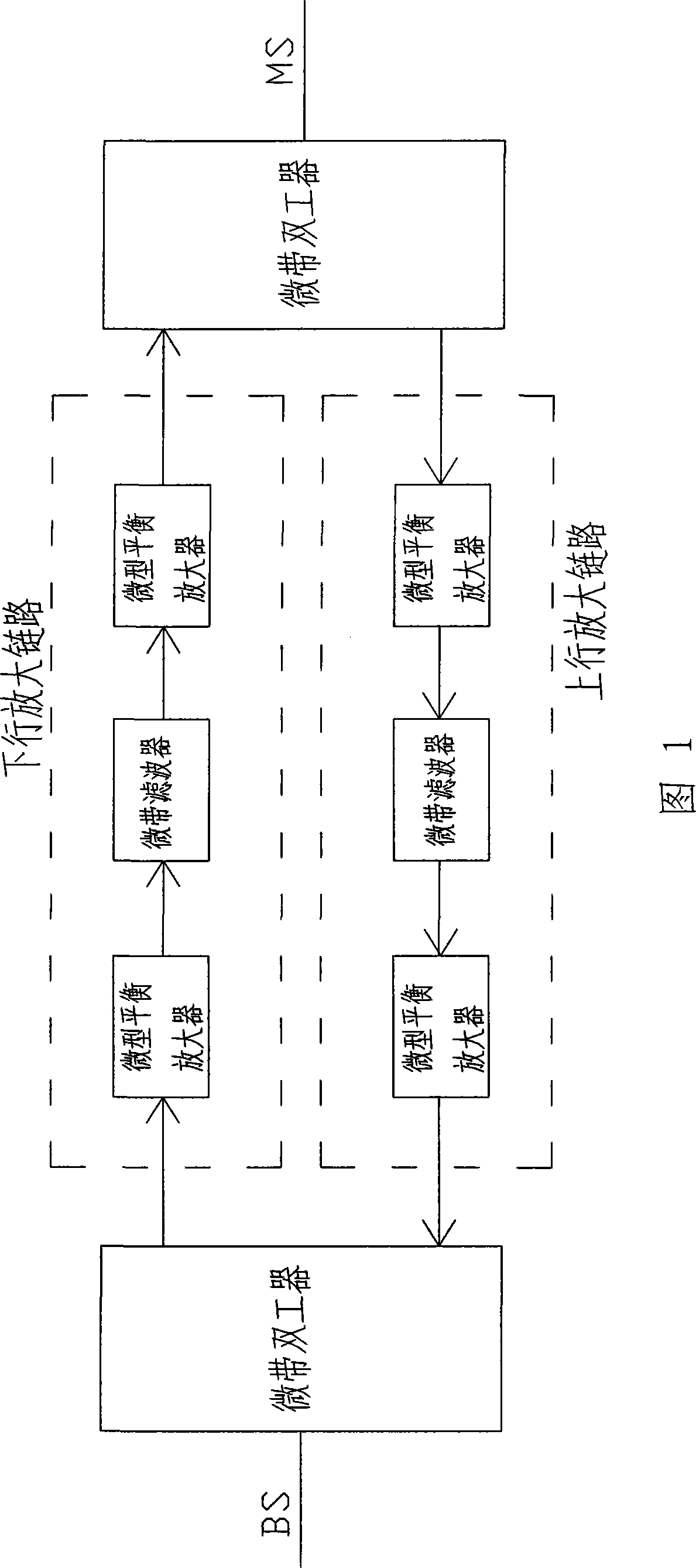
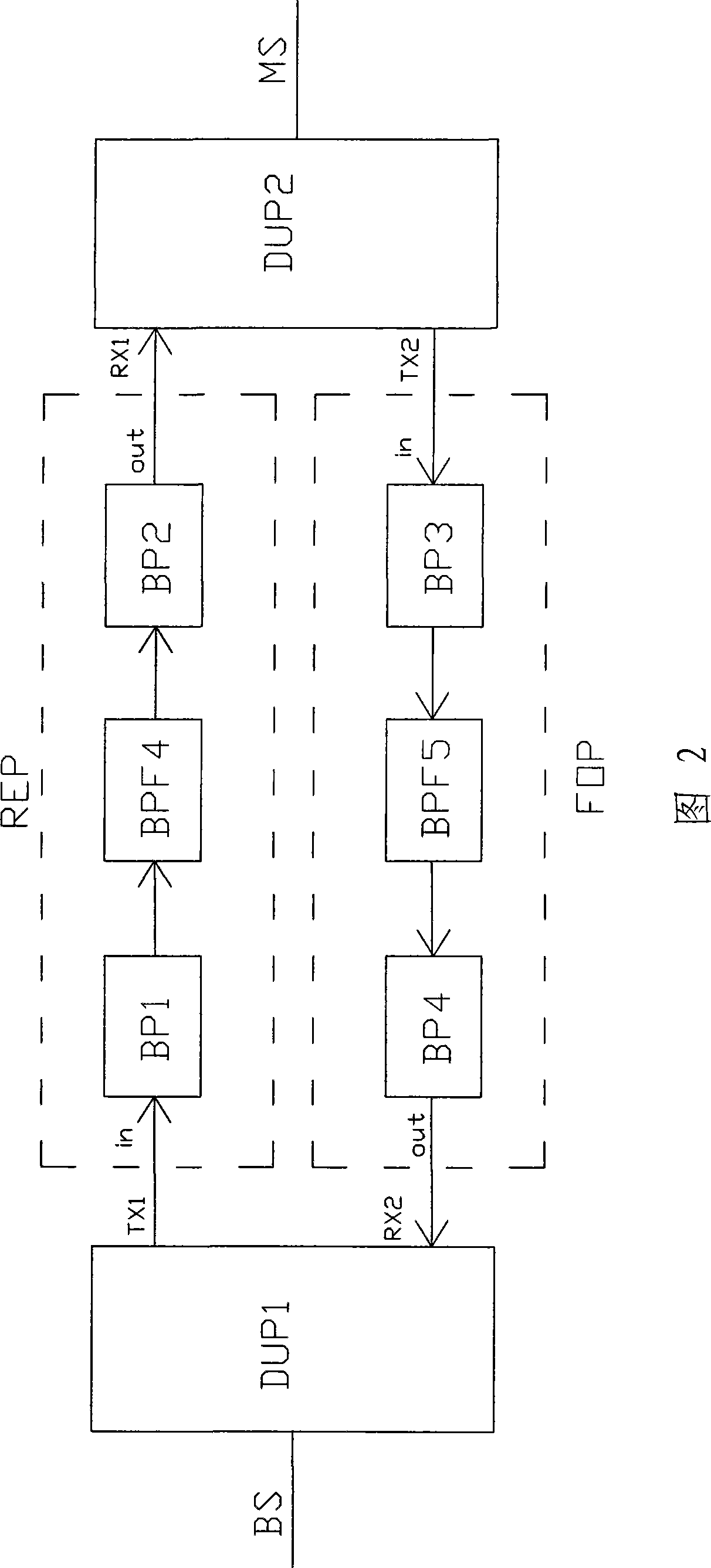
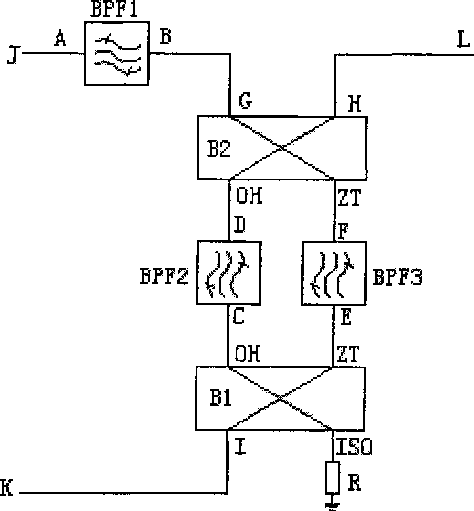
[0017] As shown in Fig. 1 and Fig. 2, the microwave low-band ultra-miniature repeater station of the present invention is made up of two microstrip duplexers DUP1, DUP2, an uplink amplifying link FOP, and a downlink amplifying link REP, and the uplink and downlink amplifying links are Microwave low-band ultra-miniature frequency-selective amplification module, take the downlink amplification link REP as an example, as shown in Figure 2, image 3 As shown, the circuit composition of the microwave low-band ultra-miniature frequency-selective amplifier module includes two-stage balanced amplifiers BP1, BP2 and microstrip band-pass filter BPF4. The radio frequency input RFin is connected to the input terminal in of the first-stage balanced amplifier BP1. The output terminal out of the first-s...


PUM


Abstract

The invention relates to a microwave low-wave band ultramicro relay station, which consists of two micro-strip duplexers, an up magnifying link and a down magnifying link. The up magnifying link and the down magnifying link are microwave low-wave band ultramicro frequency selective magnifying modules, a circuit of the up magnifying link and the down magnifying link comprises a balanced amplifier, a micro-strip band-pass filter and a balanced amplifier which are connected in turn; the down output end of a first micro-strip duplexer is connected with the input end of a primary balanced amplifier of the down magnifying link, and the output end of a secondary balanced amplifier of the down magnifying link is connected with the down input end of a second micro-strip duplexer; and the up signal output end of the second micro-strip duplexer is connected with the input end of the primary balanced amplifier of the up amplifying link, and the output end of the secondary balanced amplifier of the up amplifying link is connected with the up input end of the first micro-strip duplexer. The relay station can reach the requirement of technical indexes of the complete machine such as up and down suppression of the complete machine and so on by adopting the high selectivity performance of the micro-strip duplexers and the micro-strip band-pass filter, and reduce the volume by tens of times compared with the prior relay station.

Description

technical field [0001] The invention relates to a microwave low-band ultra-miniature relay station, which is suitable for relay equipment for radio frequency signal transmission in the field of radio communication. Background technique [0002] With the rapid development of mobile communication, there are characteristics such as large service area, wide area, and scattered users. Suburbs, counties, towns, villages, and highways, etc., if they are all covered by base stations, will inevitably lead to problems such as large investment and low channel utilization. In addition, due to the influence of some natural and man-made factors (such as mountains, large buildings, tunnels and underground facilities, etc.), it also brings great difficulties to communication. In order to solve the above problems, radio frequency signal relay station is widely used in GSM, CDMA, WCDMA and other communication systems, because it can effectively solve the problem of signal extension and cover...

Claims


Application Information

Patent Timeline
Patent Type & Authority Applications(China)
IPC IPC(8): H04B7/14
Inventor 庄昆杰陈天佑
Owner SHENZHEN GRENTECH CO LTD
Why Eureka
Try Eureka