Surface coated long persistence phosphor and preparation thereof

A long-lasting phosphor and surface coating technology, which is applied in chemical instruments and methods, luminescent materials, etc., can solve the problems of easy aggregation, high oil absorption rate, poor compatibility, etc., achieve strong film binding force and reduce oil absorption rate , the effect of viscosity reduction

Active Publication Date: 2009-05-27
JIANGSU BREE OPTRONICS CO LTD
View PDF8 Cites 8 Cited by
  • Summary
  • Abstract
  • Description
  • Claims
  • Application Information

AI Technical Summary

Problems solved by technology

[0007] The technical problem to be solved in the present invention is to provide a surface-coated long-lasting phosphor for the problems of poor compatibility, e

Method used


Image

  • Surface coated long persistence phosphor and preparation thereof
  • Surface coated long persistence phosphor and preparation thereof
  • Surface coated long persistence phosphor and preparation thereof

Examples


Embodiment 1

[0035] Select the chemical structure as Sr 0.95 Al 2 O 4 :Eu 0.02 , Dy 0.03 The long afterglow phosphor phosphor powder of ”is used as the coating object. Weigh 150g phosphor powder and place it in a container with a heating jacket. While stirring, heat the phosphor powder to 100°C, add 0.23g stearic acid, and continue to keep warm. After stirring for 5 minutes, take 0.3 g of isopropyl bis(glyceryl distearate) aluminate, pulverize and add to the phosphor, continue to stir for 5 minutes, stop heating, and cool to room temperature to obtain the coated Phosphor.

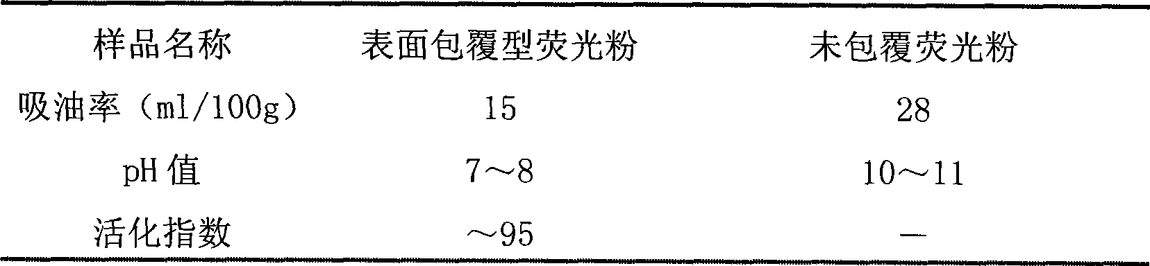
[0036] Table 1 Performance comparison before and after phosphor coating

[0037]

[0038] Table 1 lists several important performance indexes of the surface-coated phosphors and uncoated phosphors prepared in Example 1. It can be seen from the table that after surface coating, the phosphor oil absorption rate is effectively reduced, and the activation index is significantly increased.

Embodiment 2

[0040] Weigh the chemical structural formula as Sr 0.88 Al 2 O 4 :Eu 0.035 , Dy 0.085 Put 300g of the long afterglow phosphor phosphor powder in a container with a heating jacket, while stirring, heat the phosphor powder to 120℃, add 1.5g stearic acid, continue to keep warm and stir for 10 minutes, then take 3.6g Di(distearin diethylene glycol ester) isopropyl aluminate is pulverized and added to the phosphor. After stirring for 8 minutes, the heating is stopped, and the coated phosphor can be obtained by cooling to room temperature.

Embodiment 3

[0042] Take the chemical structural formula as Sr 3.982 Al 14 O 25 :Eu 0.006 , Dy 0.012Put 200g of the long afterglow phosphor powder in a container with a heating jacket. While stirring, heat the phosphor powder to 130°C, add 2.5g stearic acid, continue to keep the temperature and stir for 15 minutes, and then take 6.4g two ( The pentaerythritol tristearate (pentaerythritol ester) isopropyl aluminate is crushed and added to the phosphor. After stirring for 15 minutes, the heating is stopped, and the coated phosphor is obtained by cooling to room temperature.


PUM


Abstract

The invention relates to surface-covering type long afterglow fluorescent powder and a preparation method thereof. The fluorescent powder used for a nuclear body is alkaline-earth aluminate fluorescent powder; the fluorescent powder has a chemical structural formula of Sr (1-x-y) Al2O4:Eux, Dyy (x is more than or equal to 0.001 and less than or equal to 0.05, y is more than or equal to 0.001 and less than or equal to 0.1), Sr (4-x-y) Al14O25:Eux,Dyy (x is more than or equal to 0.0005 and less than or equal to 0.04, y is more than or equal to 0.0001 and less than or equal to 0.08) or Ca (1-x-y) Al2O4:Eux, Ndy (x is more than or equal to 0.001 and less than or equal to 0.06,y is more than or equal to 0.001and less than or equal to 0.1); and a shell layer is an organic covering layer. The organic surface modification technology is adopted to realize surface organification on the fluorescent powder, remarkably improves the compatibility between the fluorescent powder and an organic medium, and promotes the using property of the fluorescent powder. The method for manufacturing a covering layer on the surface of the fluorescent powder has a simple process and is controllable and easy to popularize and apply.

Description

Technical field [0001] The invention relates to a fluorescent powder and a surface modification method thereof, in particular to a surface-coated long afterglow fluorescent powder and a preparation method thereof. Background technique [0002] With the development of science and technology, long afterglow luminescent materials have received increasing attention, and they have a wide range of practical applications in the fields of aviation instrumentation, coating industry, enamel, textile industry and arts and crafts. It is particularly noteworthy that when long afterglow is used for road lighting, architectural signs, and fire signs, it can effectively solve the low-light illumination during short-term power outages caused by sudden accidents such as earthquakes and fires, and provide people with escape instructions and rescue People live. [0003] Different from the early sulfide luminescent materials, the SrAl2O4:Eu2+ phosphor discovered in the 1960s has entered a new stage i...

Claims


Application Information

Patent Timeline
IPC IPC(8): C09K11/02C09K11/80
Inventor 梁超何锦华张超符义兵
Owner JIANGSU BREE OPTRONICS CO LTD
Why Eureka
Try Eureka