Cutting method of fragile material substrate

A brittle material substrate and cutting method technology, applied in glass cutting devices, stone processing equipment, fine working devices, etc., can solve the problem of uncertainty of the initial micro-crack direction, reduce laser power, ensure cutting speed, and ensure cutting quality effect

Inactive Publication Date: 2009-06-03
ZHEJIANG UNIV OF TECH
View PDF2 Cites 25 Cited by
  • Summary
  • Abstract
  • Description
  • Claims
  • Application Information

AI Technical Summary

Problems solved by technology

[0005] There are two main problems with the laser cutting method proposed in patents CN1454858A, CN101121220A, etc.: first, the direction of the initial micro-cracks is uncertain; The cutting force requires a higher power laser and a stronger cooling system to form a large thermal stress

Method used


Image

  • Cutting method of fragile material substrate
  • Cutting method of fragile material substrate
  • Cutting method of fragile material substrate

Examples


example 1

[0021] Example 1 Liquid crystal glass cutting using liquid nitrogen as cooling medium

[0022] In the first step, a liquid crystal glass substrate with a thickness of 0.7mm and a size of 2850×3050mm is provided.

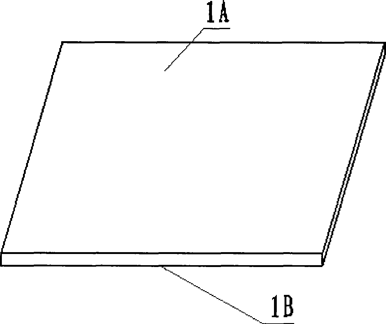
[0023] The second step, such as figure 1 shown. One surface 1A of the liquid crystal glass substrate is selected as the laser irradiation heating surface, and this plane is called the main surface.

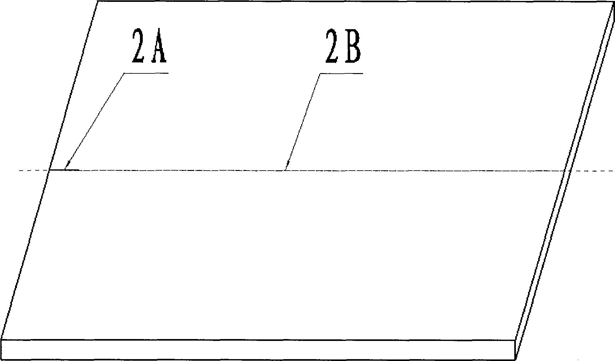
[0024] The third step, such as figure 2 shown. A slit with a length of 10 mm and a width of 0.1 mm is produced along the cutting direction along the edge of the main surface, and this slit is a penetrating initial slit.

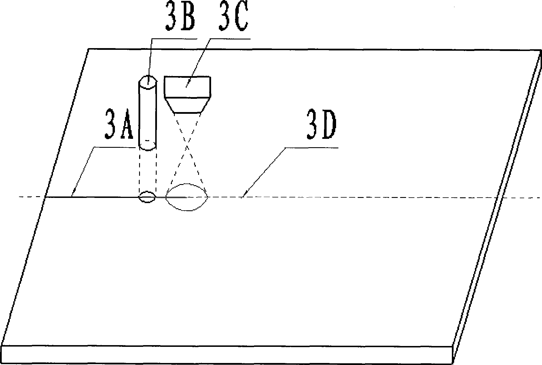
[0025] Here, a carbon dioxide laser with a wavelength of 10.6 μm is used. The distance between the laser head and the glass substrate is 30 cm. It is irradiated on the liquid crystal glass to form a circular spot with a diameter of 0.1 mm, and a penetrating laser spot with a length of 1 cm and a width of 0.1 mm is cut out. initial gap.

[0026] T...

example 2

[0030] Example 2 Ultra-clear glass cutting using jet water as cooling fluid

[0031] The first step is to provide an ultra-clear glass substrate with a thickness of 1.8mm and a size of 200×400mm.

[0032] The second step, such as figure 1 shown. One surface of the liquid crystal glass substrate is selected as the laser irradiation heating surface, which is called the main surface, which is the plane pointed by 1A here; the opposite side of 1A is 1B, which is called the secondary surface here.

[0033] The third step, such as figure 2 shown. A slit with a length of 10 mm and a width of 0.1 mm is produced along the cutting direction along the edge of the main surface, and this slit is a penetrating initial slit.

[0034] Here, a carbon dioxide laser with a wavelength of 10.6 μm is used. The distance between the laser head and the glass substrate is 30 cm. It is irradiated on the liquid crystal glass to form a circular spot with a diameter of 0.1 mm, and a penetrating laser ...


PUM

PropertyMeasurementUnit
thicknessaaaaaaaaaa
lengthaaaaaaaaaa
widthaaaaaaaaaa

Abstract

The invention discloses a cutting method of a fragile material substrate. The cutting method comprises the following steps: firstly, irradiating and heating edges of the fragile material substrate along a predetermined cutting direction by a laser beam A with the power of 30-50W to manufacture an initial penetrable slit the length of which is not longer than 20mm and the width of which is shorter than 0.01mm; then irradiating to heat the substrate from the tip of the initial penetrable slit along the predetermined cutting direction by a laser beam B with the power of 5-15W, and subsequently performing forced cooling on the fragile material substrate by a coolant to cause the fragile material substrate to crack along the predetermined cutting direction. The cutting method of the fragile material substrate can help greatly reduce the power of the laser for the subsequent cutting by obtaining the initial penetrable slit, and ensure the cutting quality and the cutting speed, wherein, surface roughness of a cut side of a liquid crystal glass substrate is 50mum or less.

Description

(1) Technical field [0001] The invention relates to a method for cutting a brittle material substrate by laser irradiation and forced cooling, and is especially suitable for cutting liquid crystal glass. (2) Background technology [0002] There are two main methods for cutting liquid crystal glass: one is mechanical cutting, which usually adopts the mechanical cutting method of diamond grinding wheel sheet or hard alloy wheel scribing cutting. The biggest disadvantage of the traditional mechanical cutting method is the need for post-processing procedures such as grinding and cleaning of the processed edges; in addition, due to the mechanical cutting force, micro-cracks will be generated at the edge of the cut glass; the second method is The fusing method uses a laser to generate a local high temperature to melt (vaporize) the material and separate it. With this method, the high thermal stress and residual thermal stress caused by the extremely high temperature gradient will...

Claims


Application Information

Patent Timeline
Patent Type & Authority Applications(China)
IPC IPC(8): B23K26/38B23K26/40C03B33/09B28D5/04
Inventor 周国斌黄鲜萍卢炎麟
Owner ZHEJIANG UNIV OF TECH
Why Eureka
Try Eureka