
Internal combustion type heating rotating cone type biomass pyrolysis liquefaction device

A biomass pyrolysis, heating and rotating technology, used in biofuels, special forms of dry distillation, petroleum industry, etc., can solve the problems of strict requirements on feed particle size, reduced bio-oil yield, high-temperature sand wear, etc. The effect of good particle size adaptability, improving bio-oil yield, reducing energy consumption and cost

Active Publication Date: 2012-11-21
ANHUI WEIDA ENVIRONMENTAL PROTECTION TECH
View PDF0 Cites 0 Cited by
  • Summary
  • Abstract
  • Description
  • Claims
  • Application Information

AI Technical Summary

Problems solved by technology

The problem with this method is: the combustion of the two by-products will produce water vapor, and the water vapor will eventually be condensed into the bio-oil along with the pyrolysis gas, thereby having a great impact on the quality of the bio-oil; There will be residual oxygen, and the presence of oxygen will change the pyrolysis pathway of biomass and greatly reduce the yield of bio-oil; and the gases generated by combustion will also undergo heating and cooling processes. In addition, these gases also dilute the pyrolysis process. The non-condensable gas produced greatly reduces its calorific value, which brings difficulties to its application
The technical difficulty lies in the control of sand circulation and temperature
In addition, since the circulation of sand is generally very large, the energy consumption of the circulation process and the wear caused by high-temperature sand must be considered.
The fourth is to use the high-temperature flue gas from the combustion of by-products to flow through a special reactor, such as the outer wall air interlayer of the fluidized bed, to provide the required heat for the pyrolysis reaction. This method can avoid the influence of the flue gas on the pyrolysis products. However, the heat transfer for biomass pyrolysis is limited and the thermal efficiency is low
[0004] At present, the reactors used to realize the pyrolysis and liquefaction of biomass are mainly fluidized bed reactors, which have the advantages of high heat transfer rate and short particle residence time, which is conducive to improving the efficiency of biomass pyrolysis to produce liquid fuels. It requires strict requirements on the feed particle size and requires fine processing, which complicates the material pretreatment before biomass pyrolysis and increases the cost
[0005] The above-mentioned defects in the process of biomass pyrolysis and liquefaction have greatly affected the cost of biomass oil produced by biomass pyrolysis and liquefaction, and restricted the industrial application of existing biomass pyrolysis and liquefaction technology

Method used


Image

  • Internal combustion type heating rotating cone type biomass pyrolysis liquefaction device

Examples


Embodiment Construction

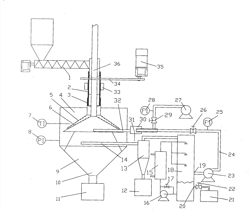
[0033] see figure 1 , using a rectangular or cylinder shaped reactor 4, two concentric cones are set inside the reactor 4, the outer cone is a rotating cone 5 rotating around the axis, and the inner cone is a fixed fixed cone 6; The section is set as the upper barrel 2 and the lower barrel 3, the upper part of the rotating cone 5 is connected with the lower barrel 3, the upper barrel 2 is connected with the screw feeding mechanism 1; the upper part of the fixed cone 6 is connected with the flue gas pipe 36 The end face of the bottom of the fixed cone 6 is closed, and its lower part communicates with the combustion pipe 32 tangentially; a porous filter tube 14 is set in the reactor 4, and the other end of the porous filter tube 14 leads out of the reactor, and is connected with the cyclone outside the reactor. The dust collector 13 is connected, the bottom output terminal of the cyclone dust collector 13 is connected to the carbon collection box 12, and the gas outlet at the to...


PUM


Abstract

The invention relates to an internal combustion type heating rotating cone type biomass pyrolysis liquefaction device. The device is characterized in that two concentric cones are arranged in a reactor, the outer cone is a rotating cone, and the inner cone is a fixed cone; a charging barrel is sectionally arranged into an upper section charging barrel and a lower section charging barrel, the upper part of the rotating cone is connected with the lower section charging barrel, and the upper section charging barrel is communicated with a spiral feeding mechanism; the upper part of the fixed coneis communicated with a flue gas pipeline; the end surface at the bottom part of the fixed cone is closed, and the lower part of the fixed cone is tangentially connected with a burning pipeline; a porous filter tube is arranged in the reactor, a reactor is led out form the other end of the porous filter tube, and the reactor is communicated with a cyclone dust collector positioned outside the reactor, the output end of the bottom part of the cyclone dust collector is connected with a carbon collecting box, and a gas outlet opening at the top part is connected with a condenser through a pyrolysis gas pipeline; an oil outlet opening on the condenser is communicated with an oil collecting tank, the air outlet opening of the condenser is accessed into a pyrolysis gas burner through a pyrolysisgas return pipeline. The invention realizes biomass self-heating type pyrolysis liquefaction, effectively improves the utilization ratio of the pyrolysis byproduct and reduces the total cost for biomass liquefaction.

Description

technical field [0001] The invention relates to a pyrolysis liquefaction device, more specifically a pyrolysis liquefaction device using biomass as raw material. Background technique [0002] Biomass mainly includes forestry materials, agricultural waste, municipal waste and livestock and poultry manure. Biomass is a kind of renewable energy with abundant reserves, which can be used as an alternative energy source to achieve CO 2 Zero emission and low S and N content can greatly reduce the greenhouse effect and environmental pollution. Biomass pyrolysis liquefaction refers to the direct pyrolysis of biomass under the conditions of medium temperature, high heating rate and extremely short gas residence time in the absence of oxygen, and the product is rapidly cooled to obtain high-yield liquid fuel. That is bio-oil. [0003] At present, the focus of research on biomass pyrolysis liquefaction equipment is how to better achieve efficient heat transfer and self-heating pyroly...

Claims


Application Information

Patent Timeline
Patent Type & Authority Patents(China)
IPC IPC(8): C10B53/02
CPCY02E50/14Y02E50/10
Inventor 陈天虎胡孔元张先龙刘海波蒋欣源
Owner ANHUI WEIDA ENVIRONMENTAL PROTECTION TECH
Learn More