
Surveymeter for parallelism of optical axis of visible light and infrared light wave

An infrared light, axis-parallel technology, used in the field of optical detectors, can solve the problems of low accuracy and high risk, and achieve the effect of improving measurement accuracy and reducing experimental risks.

Inactive Publication Date: 2011-02-09
INST OF OPTICS & ELECTRONICS - CHINESE ACAD OF SCI
View PDF0 Cites 0 Cited by
  • Summary
  • Abstract
  • Description
  • Claims
  • Application Information

AI Technical Summary

Problems solved by technology

[0003] The technical problem to be solved by the present invention is to provide a high-precision, low-risk detection method that can realize precise control in view of the shortcomings of the existing detection methods for the parallelism of visible and infrared light axes, which have low precision and high risk, and are only suitable for rough control. Visible and infrared light wave optical axis parallelism detector

Method used


Image

  • Surveymeter for parallelism of optical axis of visible light and infrared light wave
  • Surveymeter for parallelism of optical axis of visible light and infrared light wave
  • Surveymeter for parallelism of optical axis of visible light and infrared light wave

Examples


Embodiment Construction

[0027] The present invention will be described in detail below in conjunction with the accompanying drawings and specific embodiments.

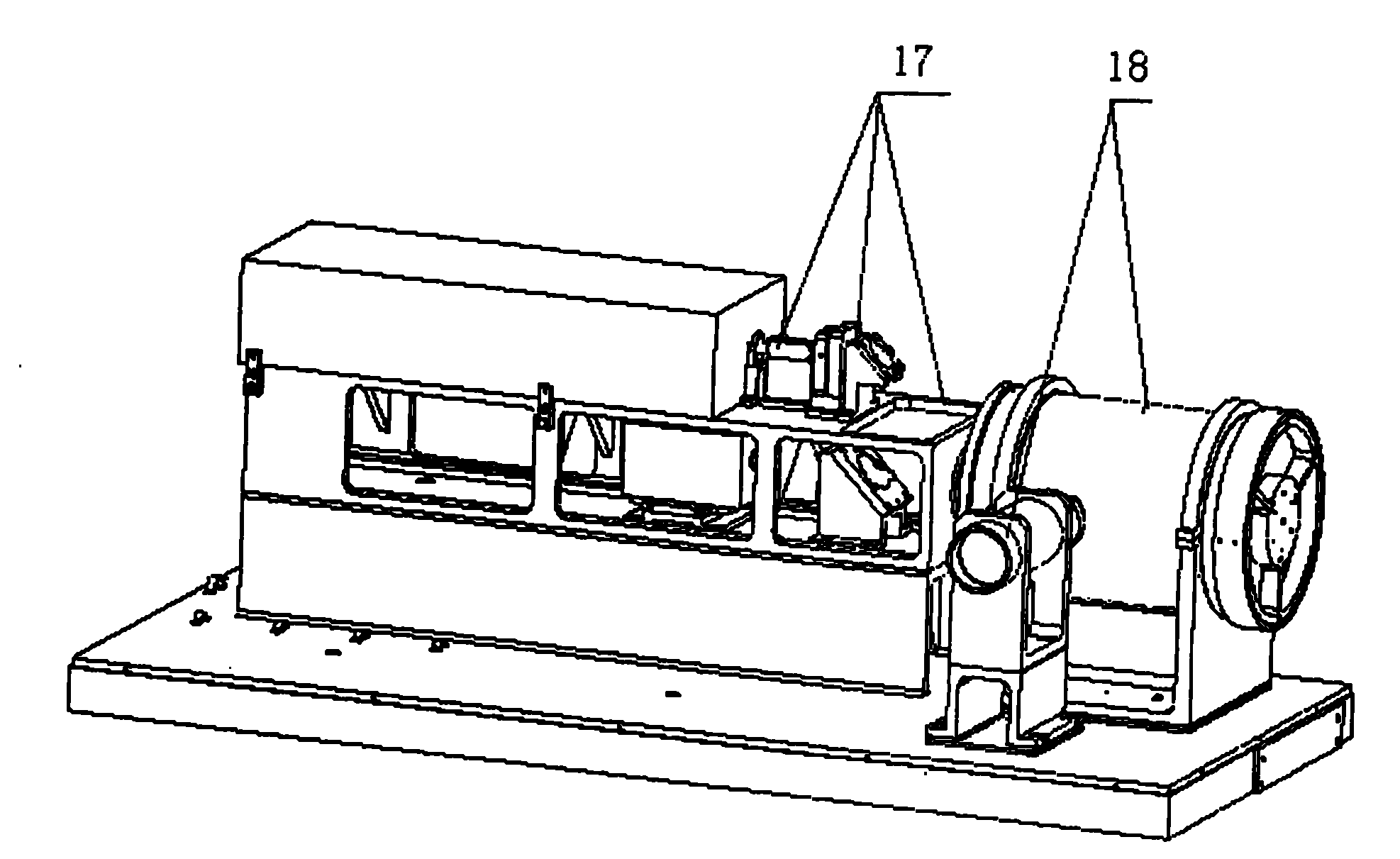
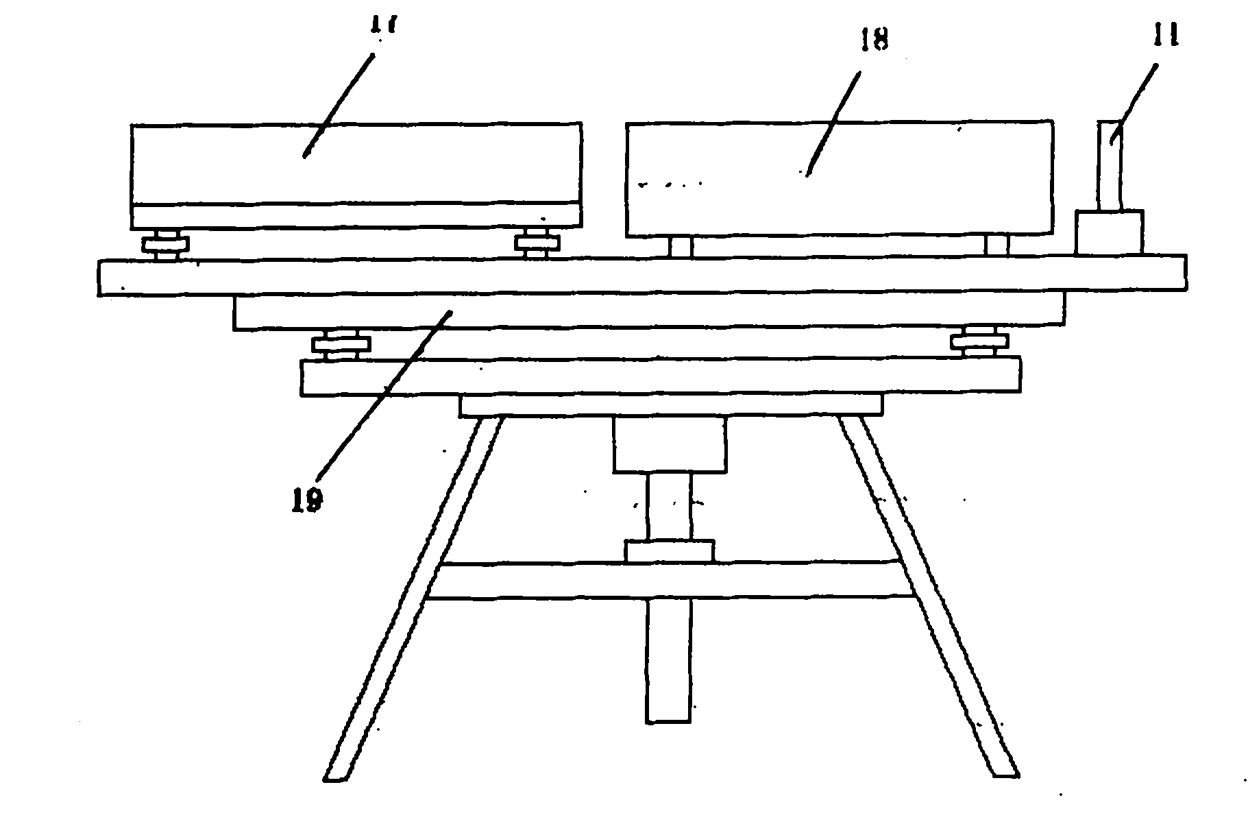
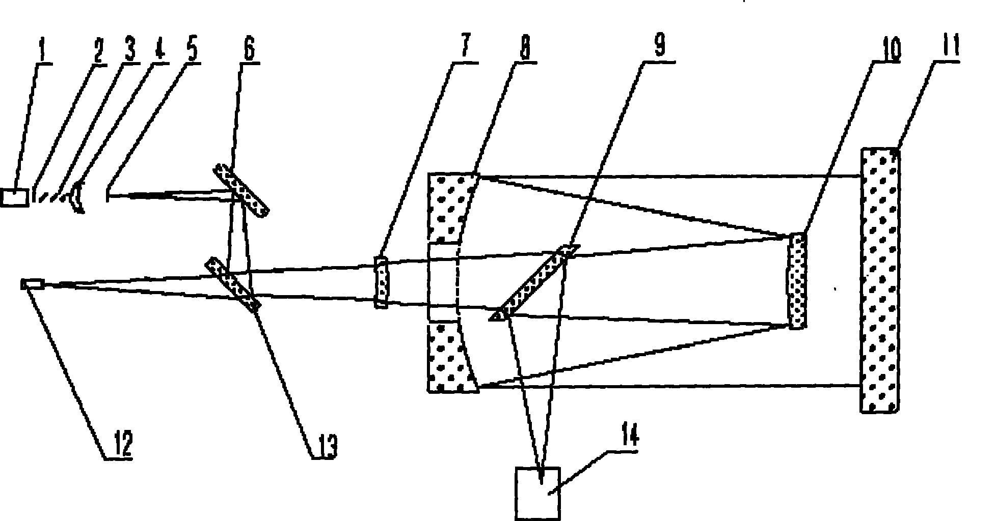
[0028] Such as figure 1 Shown is the optical system diagram of the optical axis parallelism detector for visible and infrared light waves, including infrared laser 1, variable diaphragm 2, attenuation film 3, focusing lens 4, star point 5, reflector 6, spherical mirror 7, and primary mirror 8. Infrared beam splitter 9, secondary mirror 10, standard plane mirror 11, infrared CCD 12, reflective beam splitter 13, visible light component 14; visible light component 14 includes a visible light source 14-1, cross reticle 14-2, and beam splitter 14- 3. Visible light CCD14-4; the infrared laser 1 is an infrared light source with a wavelength of 10.6 μm. The minimum diameter of the iris 2 is Φ2mm, which is used to limit the amount of infrared lasers that go through the system. The attenuation sheet 3 is an infrared material sheet coated with an att...


PUM


Abstract

The invention relates to a surveymeter for parallelism of optical axis of visible and infrared light wave, comprising an infrared light part and a visible light part. Firstly, aiming is operated by employing visible light, the visible light emitted by a visible light source lightens up a cross wire by a cross-linegraticule, an emergent visible cross wire image is formed on a visible light CCD, after being reflexed by an infrared beam splitter, a secondary mirror, a primary mirror and a standard flat mirror, the emergent visible light returns to the visible light CCD by the optical devices andforms a return cross wire image, and a system is adjusted to superpose the emergent visible cross wire image and the return cross wire image, thereby completing instrument aiming. Then infrared lightis employed for detecting, iraser emitted by an infrared laser passes through a series of optical elements of the infrared light part, and an emergent infrared spot and a return infrared spot on an infrared CCD are extracted by measurement software. Error value of the parallelism can be obtained by formula computing. The surveymeter of the invention adopts the visible light to aim and the infrared light to detect the parallelism error, thereby reducing experiment risk while improving measurement precision.

Description

technical field [0001] The invention relates to an optical detector, in particular to a detector for the parallelism of optical axes of visible and infrared light waves. Background technique [0002] Due to the needs of optical detection, some optical instruments need to work in the visible and infrared composite band; one of the main technical indicators affecting the performance of these instruments is the parallelism of the optical axes of visible and infrared light waves. The parallelism of the optical axis is strictly controlled. At present, the control method for the parallelism index of the optical axes of visible and infrared light waves is to use a piece of white paper to mark A at the focal point of visible light, use infrared light to burn a black spot on the white paper and mark it as B, and measure A and B The distance is then converted into the parallelism of the optical axes of visible and infrared light waves. This detection method has low precision and high...

Claims


Application Information

Patent Timeline
Patent Type & Authority Patents(China)
IPC IPC(8): G01B11/26G01B11/27G01M11/02
Inventor 吴时彬景洪伟杨文志曹学东
Owner INST OF OPTICS & ELECTRONICS - CHINESE ACAD OF SCI
Learn More