
High-frequency clock generator, clock frequency conversion method, and chip

A high-frequency clock and generator technology, applied in the direction of single output arrangement, signal generation/distribution, logic circuit using basic logic circuit components, etc., can solve the problems of high power consumption, high cost of digital circuits, and large occupied area. Achieve the effects of small area, cost reduction and space saving

Inactive Publication Date: 2009-06-03
VIMICRO CORP
View PDF1 Cites 11 Cited by
  • Summary
  • Abstract
  • Description
  • Claims
  • Application Information

AI Technical Summary

Problems solved by technology

Therefore, if a phase-locked loop is used in these digital circuits, the cost is relatively high, the power consumption is large, and the occupied area is large, resulting in high cost of digital circuits.

Method used


Image

  • High-frequency clock generator, clock frequency conversion method, and chip
  • High-frequency clock generator, clock frequency conversion method, and chip
  • High-frequency clock generator, clock frequency conversion method, and chip

Examples


Embodiment Construction

[0034] In order to make the above objects, features and advantages of the present invention more comprehensible, the present invention will be further described in detail below in conjunction with the accompanying drawings and specific embodiments.

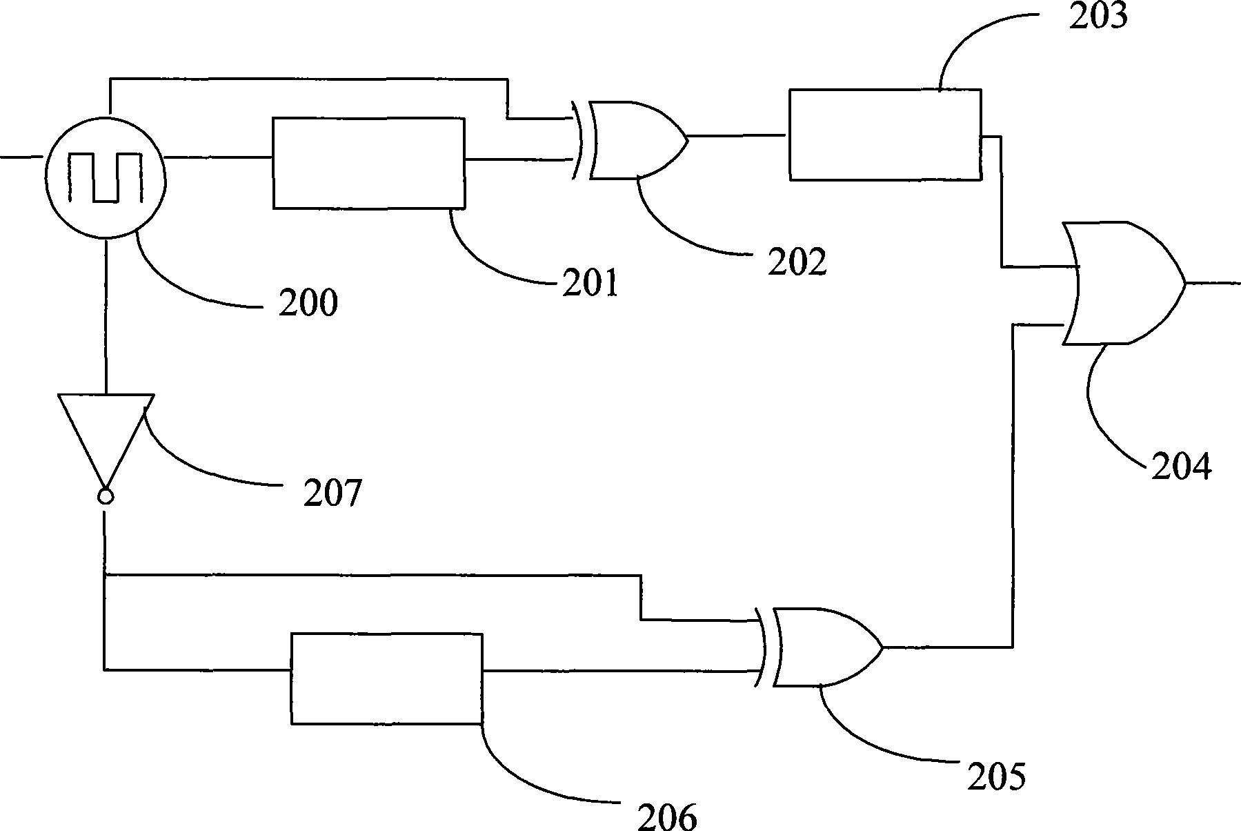
[0035] The core idea of ​​the present invention is to use a logic gate circuit and a delayer to form a high-frequency clock generator instead of a phase-locked loop to obtain a clock with a higher frequency than the input clock; the high-frequency clock generator of the present invention can adjust the duty cycle , and occupies a small area, it can reduce the cost well when used in digital circuits.

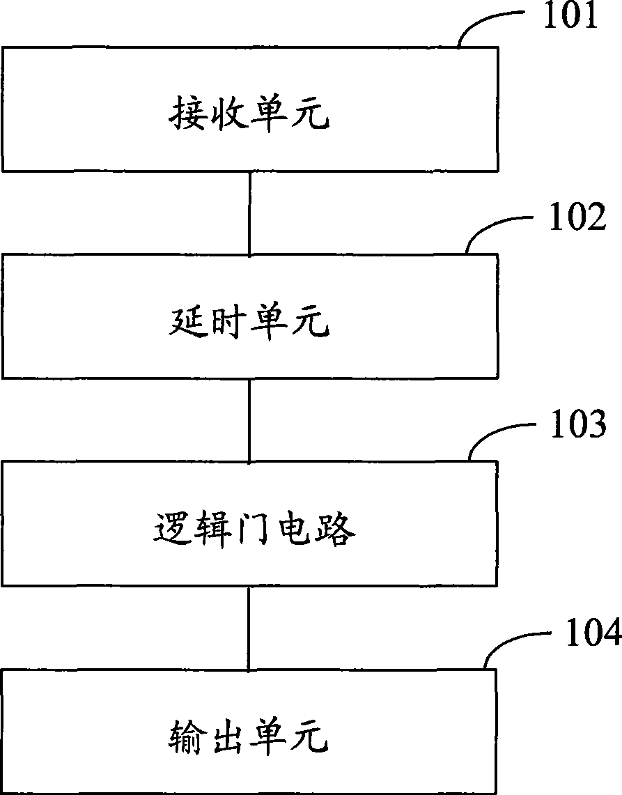
[0036] refer to figure 1 , shows a structural block diagram of a high-frequency clock generator of the present invention, the high-frequency clock generator includes the following units:

[0037] a receiving unit 101, configured to receive a low-frequency clock signal;

[0038] a delay unit 102, configured to delay and output the l...


PUM


Abstract

The invention provides a high-frequency clock generator, a clock frequency conversion method and a chip. The high-frequency clock generator comprises a receiving unit for receiving a low-frequency clock signal; a time-delaying unit for delaying the low-frequency clock signal; a logical gate unit for logical combination of the low-frequency clock signal and the delayed low-frequency clock signal to obtain a high-frequency clock signal; and an output unit for outputting the high-frequency clock signal. The high-frequency clock generator obtains the high-frequency clock signal by combining the time-delaying unit with a logical gate circuit, and has small area and low cost, thereby reducing the cost and the power consumption of the high-frequency clock signal.

Description

technical field [0001] The invention relates to the technical field of clocks, in particular to a high-frequency clock generator, a clock frequency conversion method and a chip. Background technique [0002] In the current application of clock technology, a phase-locked loop (PLL; Phase Lock Loop) is commonly used to convert a low-frequency signal into a high-frequency signal, so as to meet requirements for clock signals in different frequency bands. The main application range of phase locked loop is generally: transmitter, receiver, signal generator, frequency synthesizer, function generator, chip interface, digital circuit, etc. [0003] The existing phase-locked loop is mainly a closed-loop circuit composed of field effect transistors, transistor oscillators, filters, etc., which can generate high-frequency clocks from low-frequency clocks and multiply the frequency by dozens of times for use in digital circuit systems. [0004] However, in the application of some simple...

Claims


Application Information

Patent Timeline
IPC IPC(8): G06F1/04H03K5/13H03K19/173
Inventor 张浩
Owner VIMICRO CORP
Learn More