
Pre-pressing horizontal refuse compressor

A garbage compression and garbage technology, which is applied in garbage conveying, garbage collection, storage devices, etc., can solve the problems of imperfect dehydration performance, incomplete dehydration, and unsatisfactory effect, so as to prevent secondary pollution, reduce garbage volume, Manpower saving effect

Inactive Publication Date: 2009-06-17
广西玉柴专用汽车有限公司
View PDF1 Cites 14 Cited by
  • Summary
  • Abstract
  • Description
  • Claims
  • Application Information

AI Technical Summary

Problems solved by technology

[0003] Yet the inventor finds after several years of market research that there are still some problems in the above-mentioned garbage compression equipment: because the dehydration performance of the current garbage compressors is not perfect, although people have made great efforts to improve in this respect, the effect It is still not ideal, especially in some southern cities with abundant rainfall and a lot of fruits and vegetables, the water content of the garbage is relatively high, and the dehydration of the garbage is not complete enough when the garbage is compressed by a general compressor, and the garbage is being transferred on the street. The phenomenon of sewage dripping occurs from time to time. As people's requirements for environmental sanitation are getting higher and higher, this requires us to make further improvements to the garbage compressor

Method used


Image

  • Pre-pressing horizontal refuse compressor
  • Pre-pressing horizontal refuse compressor
  • Pre-pressing horizontal refuse compressor

Examples


Embodiment 1

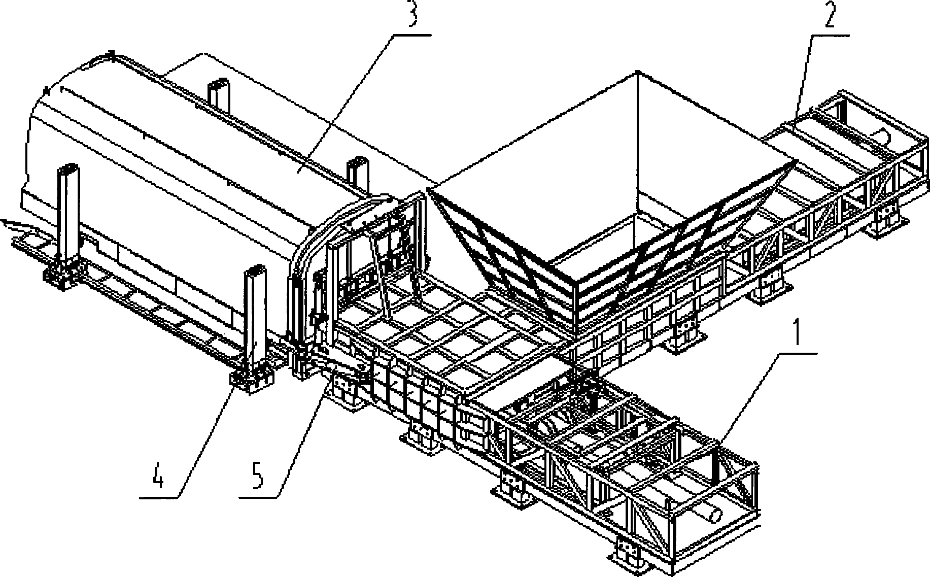
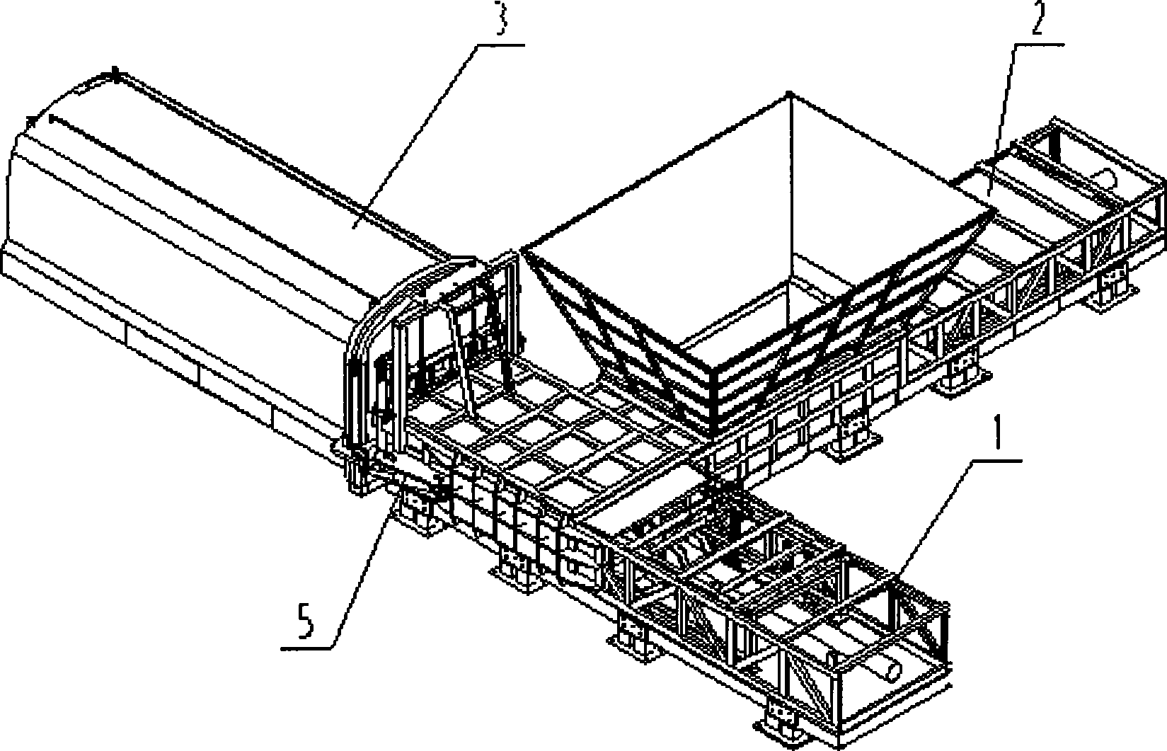
[0020] like figure 1 Shown: when the garbage needs to be collected, the garbage compartment 3 of the empty compressed garbage truck transported by the chassis of the car reverses and drives into the transfer station along the wheel guide device, stops when the wheel touches the tire limiter, turns off the power supply, and operates the hydraulic pressure The control system enables the lifting mechanism 4 to lift the garbage compartment 3 to the maximum height. The lifting mechanism 4 has four lifting towers, which are installed on the left and right sides of the garbage compartment 3 in front, rear, left, and right sides. The chassis of the car leaves the garbage collection position. Manipulate the hydraulic control system to make the lifting mechanism 4 lower the garbage compartment 3 into the garbage transfer station, close the locking mechanism 5 to make the garbage compartment 3 dock with the garbage outlet of the main compressor 1 and lock it, and operate the lifting cylin...

Embodiment 2

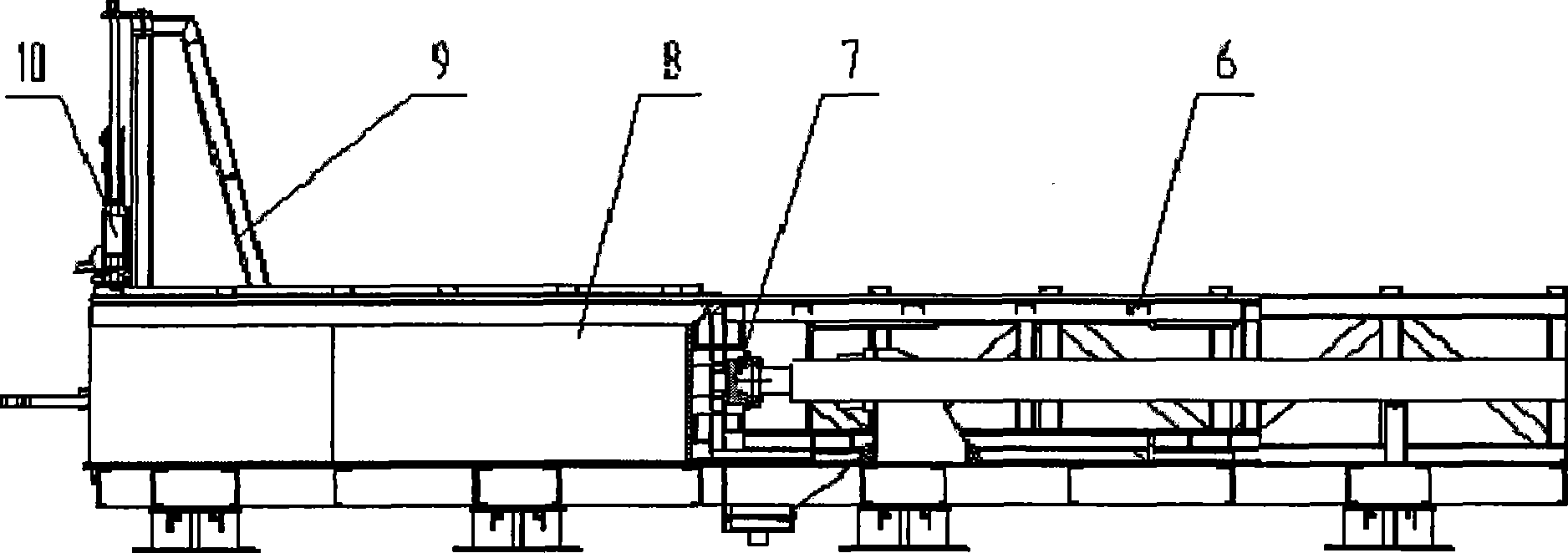
[0022] like figure 2 Shown: When the garbage needs to be collected, the chassis of the car transports the empty detachable compressed garbage compartment 3 and drives into the transfer station along the wheel guide device, stops when the wheel touches the tire limiter, and manipulates the detachable compressed garbage The pull arm mechanism of the car puts the car body on the car position; close the power supply, operate the hydraulic system, make the door of the garbage car 3 dock with the garbage outlet of the main compressor 1 and lock it, and open the lifting cylinder 10 so that the gate of the garbage car 3 Mention, at this moment, garbage truck (tricycle or post-loading compressed garbage truck, dump truck, etc.) can drive in from the car runway, stop at the unloading platform, and constantly dump the garbage, so that the garbage enters the secondary compressor from the loading hopper 14 In 2, the hydraulic system is operated, the auxiliary push head assembly 12 advance...


PUM


Abstract

The invention provides piston type prepressed horizontal garbage compressing equipment, which is characterized in that a side port of a main compressor is provided with an auxiliary compressor; and after being prepressed and dewatered by the auxiliary compressor, the garbage is compressed through a main compressing cavity so as to compress the garbage into a carriage. The equipment has the advantages of high garbage compressing efficiency, low station building cost, large garbage dewatering quantity, high efficiency, secondary pollution reduction and so on.

Description

technical field [0001] The invention relates to a sanitation garbage transfer station, in particular to a pre-compressed horizontal garbage compression device for collecting, compressing and treating garbage at the transfer station. Background technique [0002] With the progress of various urban construction and environmental sanitation management modernization, garbage recycling, reduction, harmlessness, and mass production, as well as the promotion of comprehensive environmental improvement and the implementation of projects, major and medium cities are building modern large-scale In the garbage transfer station, in the existing garbage transfer station equipment, the garbage compressor is one of the main equipment. The function of the garbage compressor is to compress, dehydrate and collect the garbage collected from the residential area into the garbage compartment. Shipped to landfill. There are many types of compressors on the market at present, and some garbage tran...

Claims


Application Information

Patent Timeline
Patent Type & Authority Applications(China)
IPC IPC(8): B65F9/00
Inventor 秦建宁覃启华杨德权邓树林颜伟才任辉陈高峰许绍华陆愈天章霞东来超英
Owner 广西玉柴专用汽车有限公司
Learn More