Laser forming electro-galvanizing wire conducting roller and manufacturing method thereof

A laser forming, conductive roller technology, applied in manufacturing tools, laser welding equipment, electrolysis process, etc., can solve problems such as affecting the overall performance of surface functional materials, affecting the service life of conductive rollers, and failing to reach an ideal level, achieving great practical value. , The production cost is low, and it is not easy to be electrically ablated.

Inactive Publication Date: 2009-06-17
SHENYANG DALU LASER TECH
View PDF0 Cites 21 Cited by
  • Summary
  • Abstract
  • Description
  • Claims
  • Application Information

AI Technical Summary

Problems solved by technology

The disadvantage of the former method is that the conductivity, corrosion resistance and wear resistance of the functional material on the surface of the conductive roller are affected by the welding performance and mechanical properties, and cannot reach the ideal level, and the structure of the weld and other parts of the surface is different. Uniformity, which often leads to the failure of the conductive roller at the welding seam, thus affecting the overall service life of the conductive roller
In addition, the process method has poor controllability, difficult operation, long manufacturing cycle, low yield and high cost
The disadvantage of the latter manufacturing method is that defects such as component segregation, pores and inclusions generated during the casting process affect the overall performance of the surface functional material, especially the corrosion resistance, thereby affecting the service life of the conductive roller

Method used


Image

  • Laser forming electro-galvanizing wire conducting roller and manufacturing method thereof

Examples


Embodiment 1

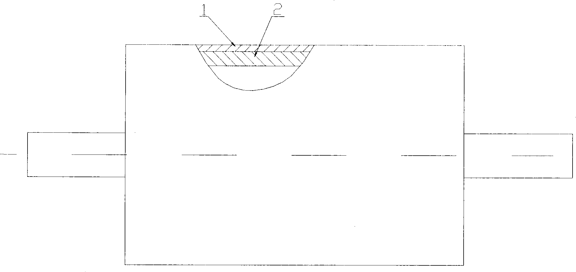
[0019] Conductive roll structure such as figure 1 As shown: the conductive roller is composed of a base 1 and a laser cladding layer 2, and the laser cladding layer 2 covers the base 1.

[0020] The process steps are as follows:

[0021] 1. Make the conductive roller base 1, and leave a 3.5mm laser cladding margin on the outer circle of the inner cylinder;

[0022] 2. Laser cladding the intermediate transition layer, using cross-flow continuous CO 2 The laser cladding a layer of nickel-based alloy powder on the outer circle of the substrate 1 as a base layer, as the intermediate transition layer, the thickness of the cladding is 0.8-0.9mm, and the main chemical composition and content (weight percentage) of the intermediate transition layer are: Mo: 15.8%, Cr: 14%, W: 3.7%, Fe: 18.5%, and the balance is Ni and a small amount of other added elements. The laser cladding process parameters are: laser power 2000W, spot diameter 2.5mm, scanning speed 5mm / s.

[0023] 3. Machinin...

Embodiment 2

[0027] Conductive roll structure such as figure 1 As shown: the conductive roller is composed of a base 1 and a laser cladding layer 2, and the laser cladding layer 2 covers the base 1.

[0028] The process steps are as follows:

[0029] 1. Make conductive roller base 1, leaving 3.0mm laser cladding margin on the outer circle of the inner cylinder;

[0030] 2. Laser cladding the intermediate transition layer, using cross-flow continuous CO 2 The laser clads a layer of nickel-based alloy powder on the outer circle of the substrate 1 as an intermediate filter layer. The cladding thickness is 0.8-0.9mm. The main chemical composition and content (weight percentage) of the intermediate transition layer are: Cr: 26%, Ni: 11%, W: 7.5%, Fe: 2.0%, the balance is Co and a small amount of other added elements. The laser cladding process parameters are: laser power 2000W, spot diameter 2.5mm, scanning speed 3.3mm / s.

[0031] 3. Machining. Remove the laser cladding scale on the surfac...

Embodiment 3

[0035] Conductive roll structure such as figure 1 As shown: the conductive roller is composed of a base 1 and a laser cladding layer 2, and the laser cladding layer 2 covers the base 1.

[0036] The process steps are as follows:

[0037] 1. Make conductive roller base 1, and leave 10mm laser cladding margin on the outer circle of the inner cylinder;

[0038] 2. Laser cladding the intermediate transition layer, using CO 2 The laser cladding three layers of nickel-based alloy powder on the outer circle of the substrate 1 as the middle filter layer, the cladding thickness is 1.9 ~ 2.0mm, the main chemical composition and content (weight percentage) of the middle transition layer are: Cr: 26%, Ni: 11%, W: 7.5%, Fe: 2.0%, the balance is Co and a small amount of other added elements. The laser cladding process parameters are: laser power 2000W, spot diameter 4mm, scanning speed 12mm / s.

[0039] 3. Machining. Remove the laser cladding scale on the surface, and ensure that the th...


PUM

PropertyMeasurementUnit
thicknessaaaaaaaaaa
thicknessaaaaaaaaaa

Abstract

A laser forming electrogalvanizing line conducting roll comprises a substrate. The surface of the substrate is coated with a laser cladding layer, the thickness of the laser cladding layer is 3-10mm, the laser cladding layer and the substrate are bonded in a metallurgical manner, and the laser cladding layer is a nickel base alloy powder layer or a cobalt base alloy powder layer or a combination of the nickel base alloy powder layer and the cobalt base alloy powder layer. A manufacturing method of the laser forming electrogalvanizing line conducting roll comprises the following working procedures: A. fabricating the substrate of the conducting roll; and B. cladding an intermediate transition layer by laser: firstly cladding a layer of the nickel base alloy powder or the cobalt base alloy powder on the substrate of the conducting roll for rendering by a transverse-flow continuous CO2 laser device as the intermediate transition layer; removing surface laser cladding oxide scale by machining, and then cladding the nickel base alloy powder or the cobalt base alloy powder with better wear resistance and corrosion resistance on the intermediate transition layer by the transverse-flow continuous CO2 laser device as a surface functional layer. The manufacturing method has the advantages of strong adaptability, simple convenient operation, high normativeness, low production cost and great practical value.

Description

technical field [0001] The invention relates to a conductive roller in electrogalvanizing production and its manufacturing technology. Background technique [0002] The conductive roller is one of the key equipments of the electrogalvanizing unit, through which the steel plate is uniformly coated with zinc. With the rapid development of the automobile industry and electrical manufacturing industry, the demand for electro-galvanized sheets continues to increase, and the quality requirements for electro-galvanized sheets are also getting higher and higher. As the key equipment of electro-galvanized The quality and production efficiency of zinc steel sheets play a vital role. [0003] At present, the conductive rollers used in my country's electrogalvanizing production lines are mainly manufactured by two processes. One is that the forged alloy steel plate is curled and welded and then hot-mounted on the surface of the standard steel inner cylinder; the other is cast on the s...

Claims


Application Information

Patent Timeline
Patent Type & Authority Applications(China)
IPC IPC(8): C25D7/06C25D17/00C23C24/10B23K26/34
Inventor 陈江刘玉兰
Owner SHENYANG DALU LASER TECH
Why Eureka
Try Eureka