
Plasma incineration waste treatment equipment

A technology of plasma and garbage incineration, which is applied in the direction of mechanical equipment, lighting and heating equipment, incinerators, etc., can solve the problems of explosion, large power consumption, and large power consumption, and achieve good safety performance, reduce power consumption, The effect of avoiding damage

Active Publication Date: 2009-06-17
GUANGZHOU SHIPYARD INTERNATIONAL LTD
View PDF0 Cites 21 Cited by
  • Summary
  • Abstract
  • Description
  • Claims
  • Application Information

AI Technical Summary

Problems solved by technology

However, in the existing plasma incineration garbage treatment equipment, the garbage is usually directly poured into the plasma incineration garbage furnace for high-temperature incineration without treatment. The poured garbage will instantly heat up, and the liquid in it will instantly vaporize and expand, causing Partial explosion may cause damage to the furnace body or electrodes of the incinerator, especially for waste with a lot of water, the impact on the furnace body and electrodes is particularly serious, such as liquid injection bottles or liquid medicine bottles in medical waste.
In addition, the electrodes of the plasma incineration garbage furnace of the existing plasma incineration garbage treatment equipment need to be connected to a high-voltage DC power supply, and the incineration process consumes a large amount of electric energy and consumes a lot of electricity

Method used


Image

  • Plasma incineration waste treatment equipment

Examples


Embodiment Construction

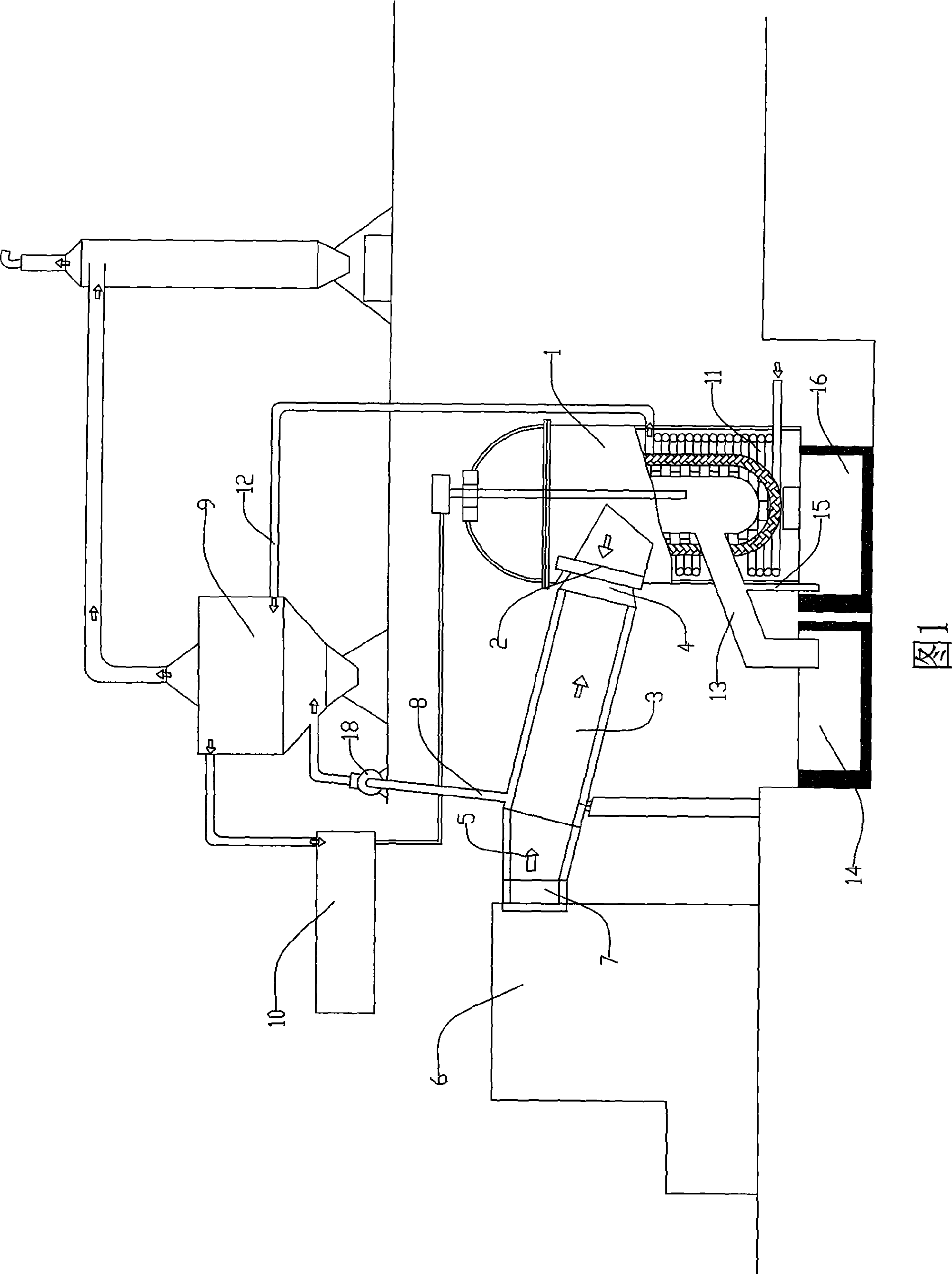
[0007] A kind of plasma incineration garbage processing equipment, as shown in Fig. 1, comprises plasma incineration garbage furnace 1, the garbage feed port 2 of the garbage incinerator is connected with the discharge port 4 of the garbage preheating device 3, and the inlet of the garbage preheating device The feed port 5 is in turn connected to the discharge port 7 of the garbage crushing device 6 . The garbage preheating device can be a horizontal rotary furnace, which is the prior art. It is inclined downward from the feed port to the discharge port, and there is a rotating device in it to drive the rotation of the garbage transported to the plasma incineration garbage furnace through its interior. . The garbage crushing device can be a pressure plate driven by a hydraulic cylinder to reciprocate up and down. The pressure plate is driven by the pressure cylinder to smash the garbage up and down repeatedly to break the garbage. It is especially easy to smash the bottles and...


PUM

PropertyMeasurementUnit
Opening widthaaaaaaaaaa

Abstract

The invention discloses plasma incineration waste disposal equipment. The waste feed inlet of a plasma waste incinerator is connected with a waste pre-heating device; the feed entrance of the pre-heating disposal device is connected with a waste crushing device; the waste pre-heating device is provided with an exhaust pipeline for mixed waste gas which is communicated with the combustion chamber of a steam boiler; the steam pipeline of the steam boiler is communicated with steam generating equipment and transmits steam to the steam generating equipment for generating power. Before entering the plasma waste incinerator, the waste is not only crushed into small pieces, but also is preheated for evaporating bulk of the moisture, so the waste entering the incinerator has small volume and less moisture, the possibility for rapidly generating excessive mixed gas and thus resulting in explosion under instant high temperature as the waste contains much water can not be generated, and the security performance is good. Meanwhile, the waste can produce a large amount of combustible mixed gas such as CO and the like in preheating, the mixed gas is conducted into the steam boiler for being incinerated and generating steam by heating, and the hot steam is transmitted into the steam generating equipment for doing work and generating electric energy which can be used for providing the electric energy that is needed by the plasma waste incinerator when in work, so the electricity consumption of the plasma incineration waste disposal equipment is also reduced.

Description

technical field [0001] The invention relates to garbage incineration treatment equipment, in particular to plasma incineration garbage treatment equipment. technical background [0002] The existing waste incineration treatment equipment usually incinerates waste mainly through the combustion furnace in the equipment. The temperature of the waste incineration is relatively low, usually only reaching about 1000°C, and the waste is often unable to be completely burned. There will be incompletely burned components remaining in the slag, and there is still a certain pollution to the environment. It cannot be used to treat medical waste, animal carcasses, chemical waste, electronic waste, dangerous goods waste and other wastes that are not allowed to remain in the slag. . In order to deal with the above-mentioned special garbage, plasma incineration garbage treatment equipment has a good prospect as a new kind of garbage treatment equipment. The incineration temperature range c...

Claims


Application Information

Patent Timeline
IPC IPC(8): F23G5/02F23G5/46F01K27/00
CPCY02E20/12
Inventor 苏汉明
Owner GUANGZHOU SHIPYARD INTERNATIONAL LTD
Learn More