
Wavelength scanning white light interferometry method based on 3*3 coupler

A technology of wavelength scanning and white light interference, which is applied in the field of wavelength scanning white light interferometry, can solve the problems that the Fourier transform white light interferophase measurement method is not suitable for high-speed measurement and low precision, and achieve high accuracy of start and stop wavelengths, high-precision measurement, and transmission peak The effect of narrow spectral lines

Inactive Publication Date: 2009-06-17
BEIJING INSTITUTE OF TECHNOLOGYGY
View PDF1 Cites 21 Cited by
  • Summary
  • Abstract
  • Description
  • Claims
  • Application Information

AI Technical Summary

Problems solved by technology

[0004] The purpose of the present invention is to solve the problem that the accuracy of the white light interference peak wavelength measurement method is not high and the Fourier transform white light interferometric phase measurement method is not suitable for high-speed measurement, and to provide a high-precision, high-speed measurement of interferometer optical path difference based on 3 × 3 Wavelength-sweeping white-light interferometry method for couplers

Method used


Image

  • Wavelength scanning white light interferometry method based on 3*3 coupler
  • Wavelength scanning white light interferometry method based on 3*3 coupler
  • Wavelength scanning white light interferometry method based on 3*3 coupler

Examples


Embodiment 1

[0033] The specific implementation of the method of the present invention applied to the measurement of the optical path difference of the Mach-Zehnder interferometer based on the 3×3 coupler is as follows.

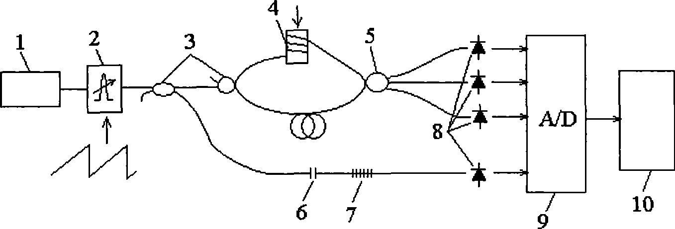
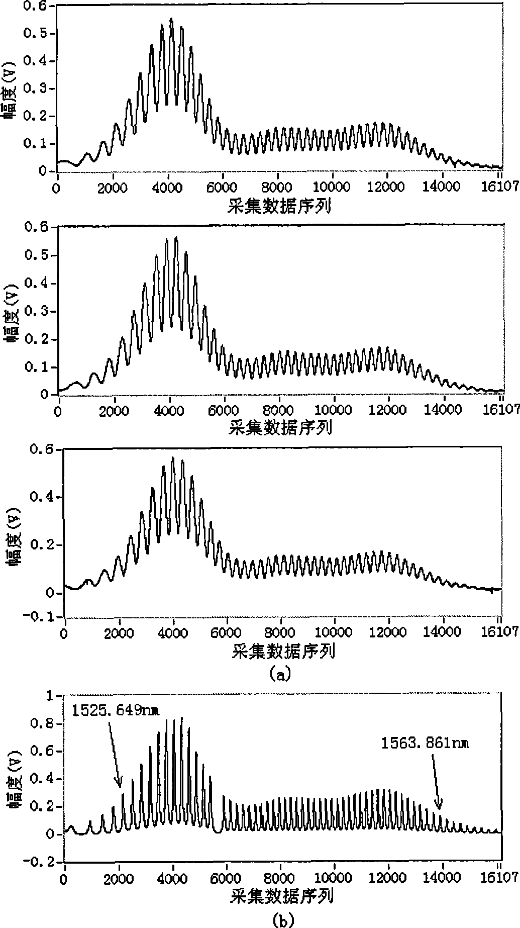
[0034] The light emitted by the broadband light source 1 is input to the tunable fiber FAP filter 2, and the tunable fiber FAP filter 2 outputs wavelength-scanning narrowband light driven by a sawtooth wave signal. The wavelength-scanning narrowband light is divided into two paths by a coupler 3, one of which is input into a Mach-Zehnder interferometer composed of a coupler 3 and a 3×3 coupler 5, and the 3×3 coupler The three output lights of 5 are detected by three photodetectors 8 respectively; The four photoelectric detection signals are collected by the A / D acquisition card 9 and input to the computer 10 for measurement.

[0035]In the embodiment, the broadband light source 1 is an ASE light source, and the spectral range covers from 1525nm to 1565nm; the free spectr...

Embodiment 2

[0041] The embodiment of the method of the present invention applied to the optical path difference measurement of the Michelson interferometer based on the 3×3 coupler is attached to the description Figure 7 shown.

Embodiment 3

[0043] The embodiment of the method of the present invention applied to the Sagnac interferometer measurement based on the 3×3 coupler is attached to the description Figure 8 shown.


PUM


Abstract

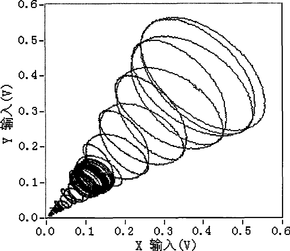
The invention relates to the technical field of fibre optical sensing, in particular to a wave length SWLI measurement technology based on a 3*3 coupler. Wave length scanning narrowband light is divided into two routes by the coupler, one route of light is input into an interferometer based on the 3*3 coupler, the other route thereof is input into an etalon and a fiber grating which are connected in series. When wave length scanning is carried out, three output white light interference spectrums of the interferometer and a transmission spectrum of the etalon and the fiber grating are probed. Start-stop wave length of wave length scanning is confirmed by the transmission spectrum of the etalon and the fiber grating, three white light interference spectrum signals have difference of 120 degrees between each two signals in phase position, a passive phase demodulation algorithm based on the 3*3 coupler can directly demodulate output phase change of the interferometer caused by wave length scanning, so as to work out absolute optical path difference. The invention has high measuring precision and can realize high-speed measurement.

Description

technical field [0001] The invention relates to the technical field of optical fiber sensing, in particular to a wavelength scanning white light interferometry technology based on a 3×3 coupler. Background technique [0002] Compared with optical fiber homodyne and heterodyne interferometry, optical fiber white light interferometry can realize the absolute measurement of interferometer optical path difference, and has significant advantages in measuring static and slowly changing physical quantities. The spectral domain white light interferometry method obtains the optical path difference of the interferometer by detecting the output white light spectrum of the interferometer. There are two ways to obtain the white light interference spectrum of the interferometer: one method is to use a broadband light input interferometer, and then use the spectrometer Probing the output spectrum of the interferometer; another approach is to use a wavelength-swept narrowband light input to...

Claims


Application Information

Patent Timeline
IPC IPC(8): G01D5/353G01J9/02G01B11/16G01G3/12
Inventor 江毅唐才杰
Owner BEIJING INSTITUTE OF TECHNOLOGYGY
Learn More