Single ingot combined automatic stop arrangement of composite twisting machine

A technology of self-stopping device and twisting machine, which is applied in textile and paper making, etc., can solve the problems of inability to meet market demand, waste of raw materials, oily yarn, inconsistent twisting length, etc., and achieves quick response, labor saving, and degree of automation. high effect

Inactive Publication Date: 2009-06-24
HANGZHOU CHANGYI TEXTILE MACHINE
View PDF0 Cites 11 Cited by
  • Summary
  • Abstract
  • Description
  • Claims
  • Application Information

AI Technical Summary

Problems solved by technology

When a broken wire fault occurs, the operator needs to find out and deal with it in time (start the manual brake mechanism to stop the spindle from rotating and reconnect the broken wire), otherwise it will easily cause the yarn to wrap around the roller and break the surrounding yarn, resulting in waste of raw materials and yarn failure. A large amount of oil-stained yarn is produced on the surface of the tube; this requires the operator to inspect continuously, which not only requires a lot of work, but also requires a lot of labor, large material consumption, low product quality, and low production efficiency.
In addition, the length of the twisted yarn produced by each spindle on this compound twisting machine is not uniform, which cannot meet the market demand

Method used


Image

  • Single ingot combined automatic stop arrangement of composite twisting machine
  • Single ingot combined automatic stop arrangement of composite twisting machine
  • Single ingot combined automatic stop arrangement of composite twisting machine

Examples


Embodiment Construction

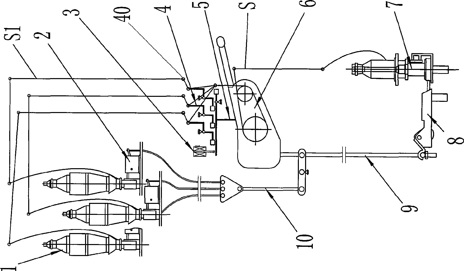
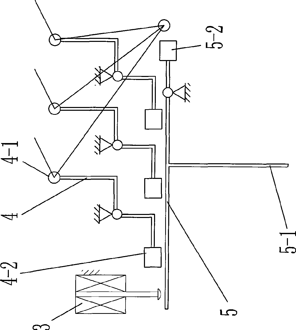
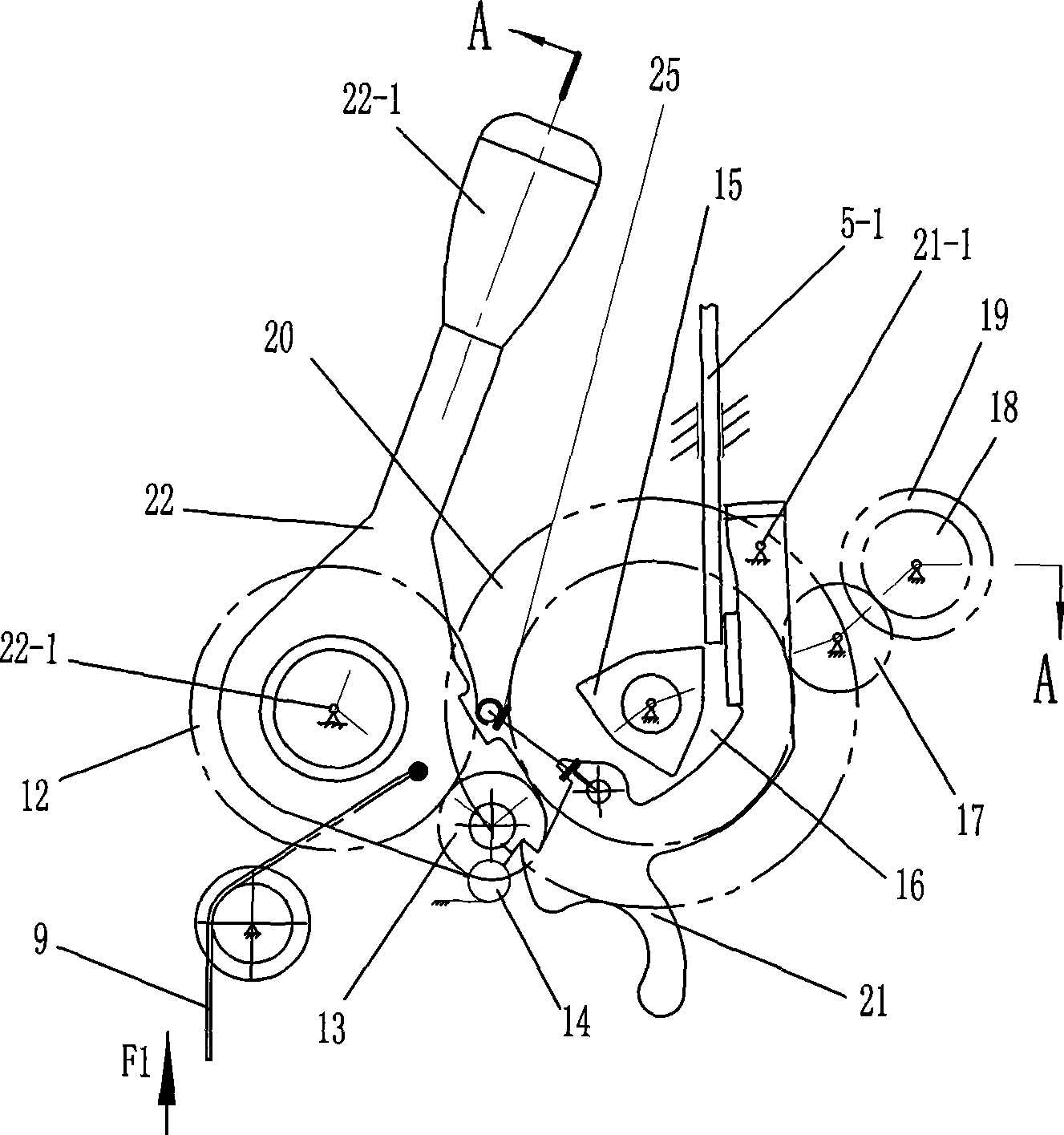
[0022] As shown in the figure, each twisting unit is equipped with the thread breakage self-stop mechanism; the mechanism includes a thread breakage detection lever 4 hinged on the frame, a trigger lever 5, a winding roller clutch, and an upper roller for the upper spindle. The brake mechanism 2, the lower brake mechanism 8 for the lower spindle and the brake wires 9 and 10 that connect the winding roller clutch with the lower brake mechanism and the upper brake mechanism to transmit the control braking force; the winding roller clutch is arranged on In the transmission case 6, comprise the gear base plate 22 that can rotate around the driving gear axis and the drag hook plate 21 that can rotate around the large roller gear axis, and a clutch gear 13 that is rotatable and meshed with the driving gear is also positioned on the gear base plate.

[0023] The wire breakage detection lever is rotatably hinged on the frame, and one end of the wire breakage detection lever is formed w...


PUM


Abstract

The invention relates to a full automatic control device of textile machinery, which solves the technical problem of leading a spindle in every twisting unit equipped with the full automatic control device to have the function of automatic stop of short yarn and full tube as well as the characteristics of rapid response, sensitive operation, accurate computation, structural durability and low cost. A composite twisting machine single spindle assembly automatic stop device also comprises a broken wire detecting rod articulated on a stander, a trigger rod positioned under the broken wire detecting rod, a piece of electromagnet used for absorbing the trigger rod and driving the trigger rod to move downwards, a winding roller clutch and an electronic detecting head installed on the clutch; a loop at one end of the broken wire detecting rod is used for being passed through by yarn, and presses the trigger rod arranged under the loop to move downwards together when the yarn is broken; the electronic detecting head send out electrical signals when the length of the twisted yarn reaches the preset standard; once receiving the electrical signals, the electromagnet immediately absorbs the trigger rod and drives the trigger rod to move downwards, and the winding roller clutch is further triggered to act and do stop operation at once.

Description

technical field [0001] The invention relates to a fully automatic control device for a textile machine, in particular to a control device for automatically stopping when the thread is broken and when the tube is full, equipped for each spindle on a compound twisting machine. Background technique [0002] The working principle of the twisting unit of the conventional compound twisting machine is as follows: Figure 7 As shown: the power output by the motor is transmitted to the driving gear in each twisting unit, and the driving gear meshes with the big roller gear coaxial with the big roller to make the big roller rotate, thus driving the combined silk yarn S to move downward (from The thread S1 unwound from the 2 or 3 upper spindles 1 respectively passes through the guide ring 40 and merges into a thread S, and then goes around the large roller 20 and the small roller 19 for several turns at the same time, and is drawn by the rotating large roller 20 Moving down), the lower...

Claims


Application Information

Patent Timeline
Patent Type & Authority Applications(China)
IPC IPC(8): D01H13/16D01H13/24
Inventor 傅岳琴沈为民
Owner HANGZHOU CHANGYI TEXTILE MACHINE
Why Eureka
Try Eureka