Charge pump DC-DC converter comprising solid state batteries

A solid-state battery, DC-DC technology, applied in the direction of output power conversion device, small flat battery/battery, no intermediate conversion to AC conversion equipment, etc.

Inactive Publication Date: 2009-06-24
NXP BV
View PDF1 Cites 8 Cited by
  • Summary
  • Abstract
  • Description
  • Claims
  • Application Information

AI Technical Summary

Problems solved by technology

However, if high efficiency is to be achieved, it is only possible to fix the conversion step, that is, when the battery voltage is at a normal value, the converter can only work at e.g. 80% efficiency
However, if the voltage is reduced by 10%, the efficiency may drop to 65%

Method used


Image

  • Charge pump DC-DC converter comprising solid state batteries
  • Charge pump DC-DC converter comprising solid state batteries
  • Charge pump DC-DC converter comprising solid state batteries

Examples


Embodiment Construction

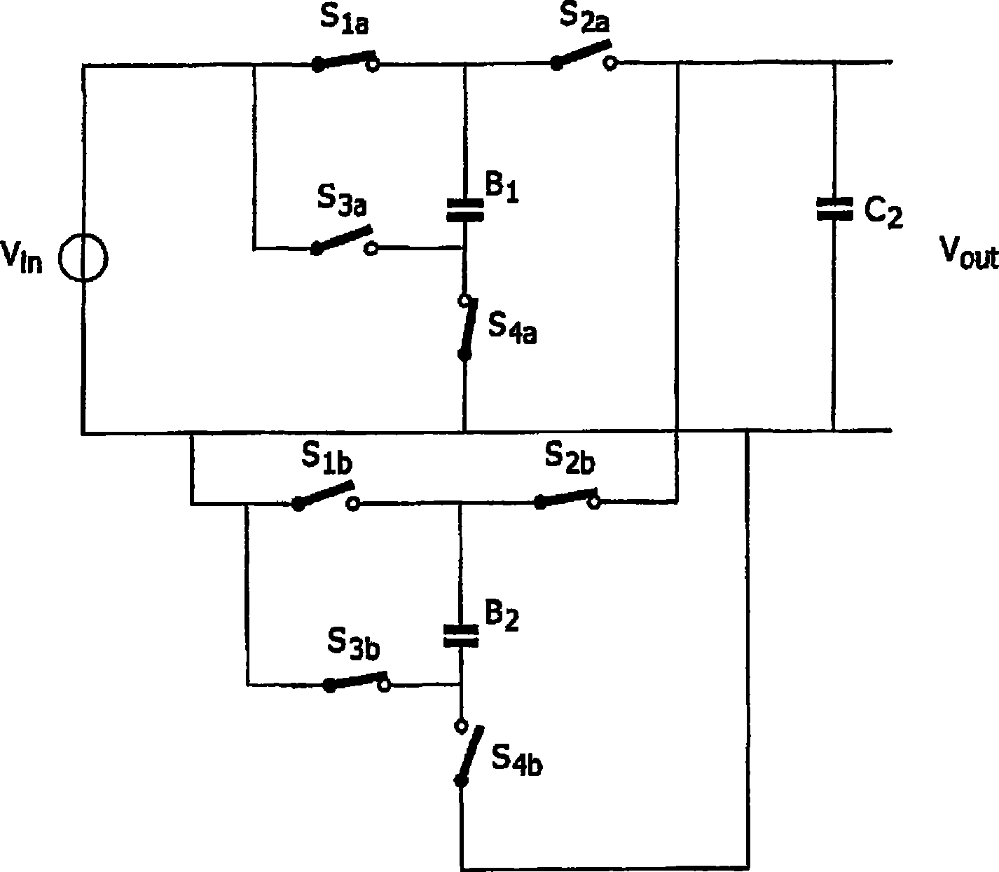
[0023] figure 2 A circuit diagram of a DC-DC converter according to the first embodiment is shown. The DC-DC converter (charge pump) comprises a first battery B1 and a second battery B2 and an output capacitor C2 at its output. In addition, the circuit includes eight switches S1a, S2a, S3a, S4a and S1b, S2b, S3b and S4b. Switches S1a, S4a, S2b and S3b are driven by a clock signal with phase p, and S2a, S3a, S1b and S4b are driven inversely by a clock signal with phase -p. Thus, if during the first half period of the clock signal the first battery B1 is partially charged and the second battery is partially discharged, the reverse is true during the second half period of the clock signal. The output capacitor C2 is used to avoid any sudden voltage drop during switching between the first battery B1 and the second battery B2. Therefore, according to the control of switching, either the first battery or the second battery is connected to the output terminal, while the other bat...


PUM


Abstract

An electronic device is provided which comprises a DC-DC converter. The DC-DC converter comprises at least one solid-state rechargeable battery (B1, B2) for storing energy for the DC-DC conversion and an output capacitor (C2).

Description

technical field [0001] The invention relates to electronic equipment with a DC-DC converter. Background technique [0002] If several different direct current (DC) voltages are required in an electronic device or integrated circuit, a DC-DC converter is usually used to step up or down the DC voltage according to the specific needs of the electronic device. [0003] DC-DC converters can use capacitors for capacitive conversion mechanisms. For inductive conversion mechanisms, coils and capacitors are usually used temporarily to store energy from switching converters. Capacitive converter technology, on the other hand, requires only capacitors for DC-DC conversion. In particular, when a DC-DC converter is implemented as an integrated circuit, the size of related devices (such as coils, capacitors, etc.) is limited so that very little energy can be stored in these devices. Therefore, switching converters are required to have a high switching frequency so that the energy in th...

Claims


Application Information

Patent Timeline
Patent Type & Authority Applications(China)
IPC IPC(8): H02M3/07H01M6/40
CPCH01M10/0562H01M10/0436Y02E60/122H01M10/425H01M10/0525H02M3/073Y02E60/10H02M3/07H02M3/155
Inventor 德克·瑞夫曼弗雷迪·罗泽博姆皮卓司·H·L·诺滕约翰·H·克洛特威克
Owner NXP BV
Why Eureka
Try Eureka