Long-focus depth super-resolution secondary confocal measuring apparatus

A measurement device and super-resolution technology, which is applied in the field of high-resolution optical microscopic measurement, can solve the problems of restricting the application of confocal measurement technology to the change of surface reflectivity, large measurement errors, and low sensitivity of axial response signal measurement.

Active Publication Date: 2009-07-01
日照菁英传媒科技有限公司
View PDF0 Cites 8 Cited by
  • Summary
  • Abstract
  • Description
  • Claims
  • Application Information

AI Technical Summary

Problems solved by technology

The basic idea is to suppress stray light by introducing a pinhole detector, and produce axial tomography capability. The shortcoming of this technology is that the measurement sensitivity of axial response signal is not high near the quasi-focus area of ​​the measurement surface, so it is only suitable for Defocus displacement measurement
However, confocal and differential confocal systems have the following problems that need to be solved urgently: First, because the principle of displacement sensing is based on the relationship between displacement and intensity, it is easily affected by factors su

Method used


Image

  • Long-focus depth super-resolution secondary confocal measuring apparatus
  • Long-focus depth super-resolution secondary confocal measuring apparatus
  • Long-focus depth super-resolution secondary confocal measuring apparatus

Examples


Example Embodiment

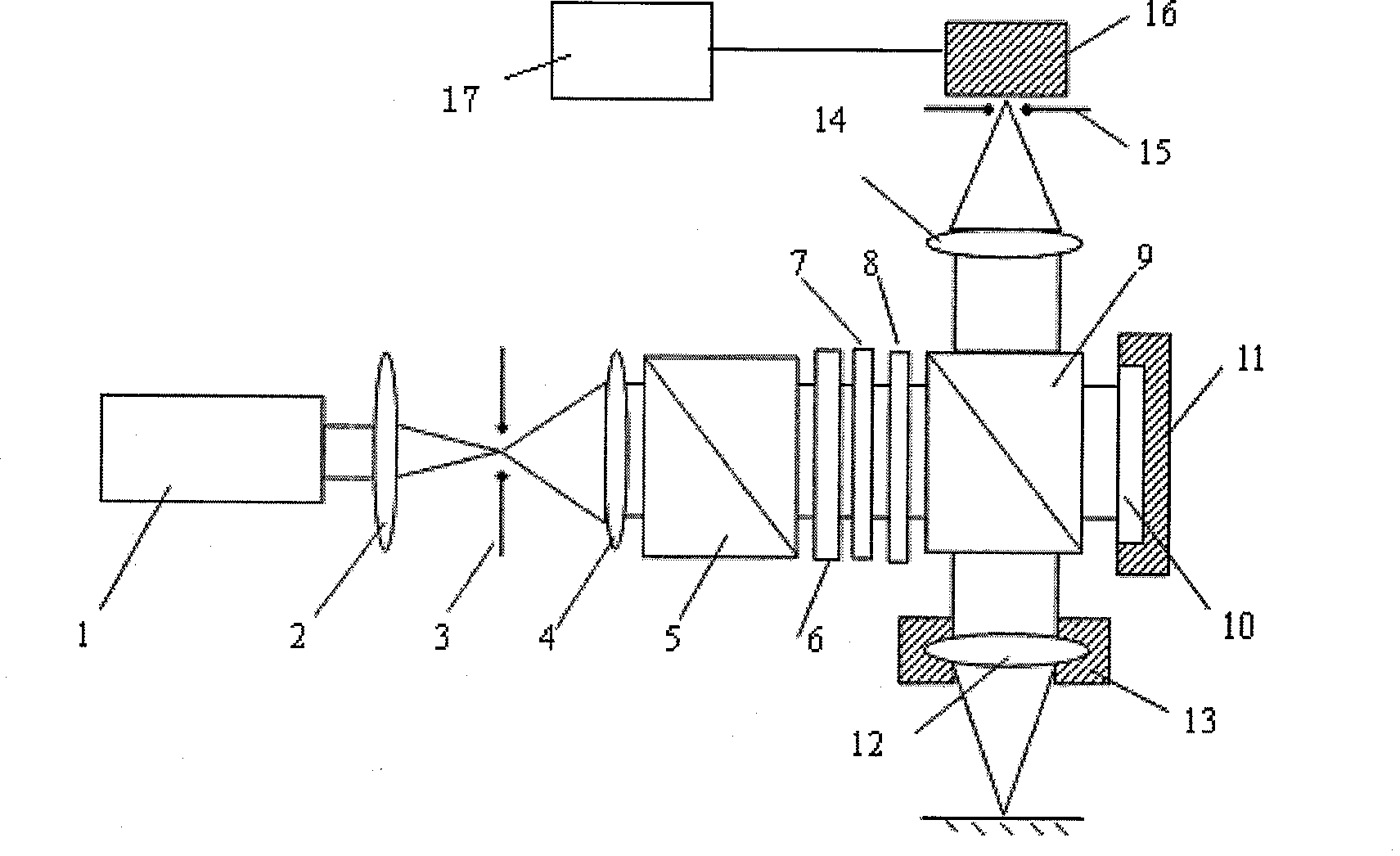
[0023] like figure 1 As shown, the secondary confocal measurement device for telephoto depth super-resolution provided by the present invention includes: laser 1; collimating and focusing objective lens 2; first pinhole 3; collimating beam expanding objective lens 4; polarizing beam splitter 5; A wave plate 6; a super-resolution filter 7; an adjustable aperture 8; a beam splitter 9; a mirror 10; Aperture 15; detector 16, and data processing means 17.

[0024] Wherein, the laser 1 emits a linearly polarized light beam, which becomes an approximately ideal plane wave after passing through the collimating beam expander lens group composed of the collimating focusing objective lens 2, the first pinhole 3, and the collimating beam expanding objective lens 4; After the quarter-wave plate 6, it becomes a circularly polarized light beam; after passing through the super-resolution filter 7, it becomes a modulated light beam carrying amplitude modulation information; the adjustable dia...


PUM


Abstract

The invention discloses a long focal length super resolution two-time confocal measuring device, comprising a laser device, a collimation extender lens group, a polarizing beam splitter, a quarter wave plate, a super resolution filter, an adjustable stop, and a splitter, which are arranged on one optical path. The long focal length super resolution two-time confocal measuring device further comprises a data processing device for attaining and recording the optical signals detected by a point detector when a focusing objective lens is driven by a micro-drive apparatus to be different positions, and converting a plurality of optical signals of the detector into phase values via four-step phase shifting method. The invention pupil filter to compress the transverse diffraction mode of measurement light spot, and expand axial diffraction mode, thereby improving transverse resolution and expanding axial measurement range without reducing axial resolution.

Description

technical field [0001] The invention belongs to the technical field of high-resolution optical microscopic measurement, and can be applied to ultra-precise non-contact rapid and large-scale scanning measurement of three-dimensional microstructure measurement, micro-step, micro-groove line width, depth and surface shape measurement. Background technique [0002] Confocal scanning measurement is one of the important technical means to measure three-dimensional microstructure, micro-step, micro-groove line width, depth and surface shape in the fields of micro-optics, micro-mechanics and micro-electronics. The basic idea is to suppress stray light by introducing a pinhole detector, and produce axial tomography capability. The shortcoming of this technology is that the measurement sensitivity of axial response signal is not high near the quasi-focus area of ​​the measurement surface, so it is only suitable for Defocus displacement measurement. The differential confocal scanning ...

Claims


Application Information

Patent Timeline
IPC IPC(8): G01B11/02G01B11/22G01B11/24G01B11/00
Inventor 刘俭谭久彬王伟波葛峥贵张大庆
Owner 日照菁英传媒科技有限公司
Why Eureka
Try Eureka