
Zero order resonator, narrow band filter and optimum design method

A zero-order resonator and narrow-band filter technology, which is applied in the microwave field, can solve problems such as the difficulty of implementing narrow-band filters, and achieve the effect of narrow bandwidth and good frequency resolution

Inactive Publication Date: 2009-07-01
INST OF ELECTRONICS CHINESE ACAD OF SCI
View PDF0 Cites 22 Cited by
  • Summary
  • Abstract
  • Description
  • Claims
  • Application Information

AI Technical Summary

Problems solved by technology

[0006] In order to solve the problem that the existing narrowband filter technology is difficult to realize, the purpose of the present invention is to use the structure of complementary split resonators (CSRRs) to design a new type of zero-order resonator, the susceptance slope parameter of the resonator is smaller than that of ordinary The band resonator is much larger, on this basis, utilize this resonator to synthesize novel narrow-band band-pass filter, for this reason, the present invention provides a kind of zero-order resonator, narrow-band band-pass filter and optimal design method

Method used


Image

  • Zero order resonator, narrow band filter and optimum design method
  • Zero order resonator, narrow band filter and optimum design method
  • Zero order resonator, narrow band filter and optimum design method

Examples


Embodiment approach

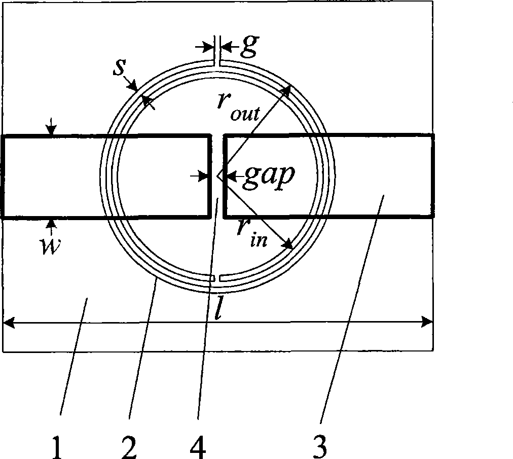
[0046] Assume that the center frequency of the filter to be implemented in this specific example is f 0 =1.98GHz, the relative bandwidth is 2.4%.

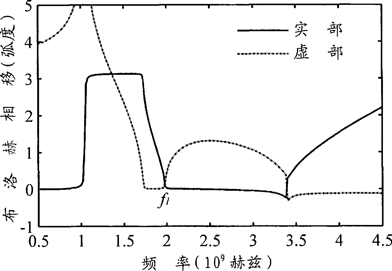
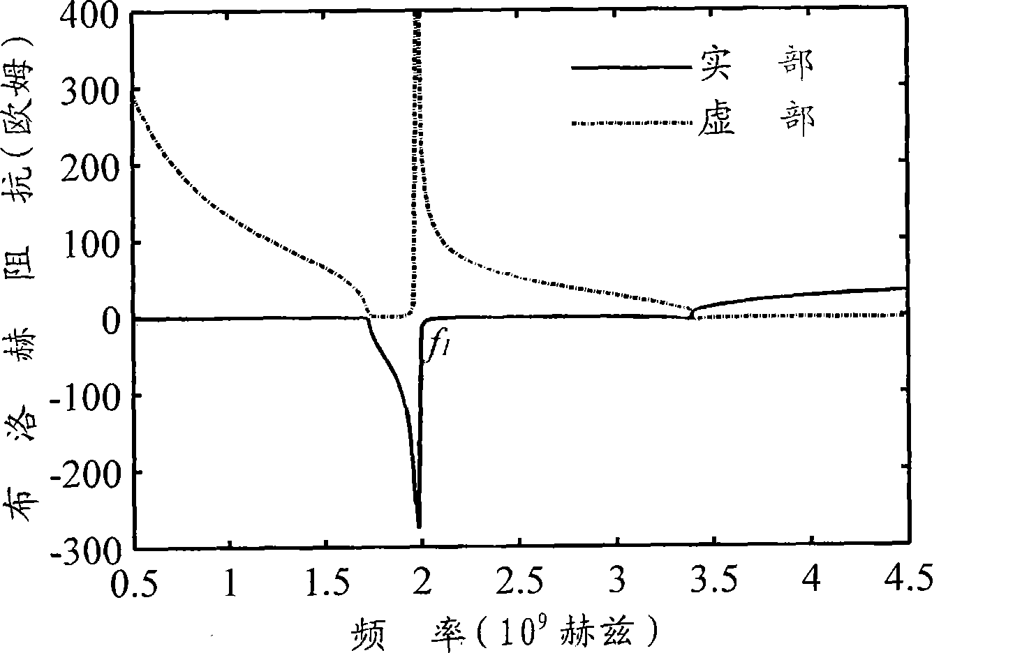
[0047] Step 1: In figure 1 The following parameter r is used in out = 6mm, r in =5.4mm, s=0.3mm, g=0.3mm, gap=0.8mm, l=22mm, w=4.2mm, as the initial value. Using the commercial software Ansoft Designer to figure 1 The two-port network shown is subjected to electromagnetic simulation to obtain its S-parameters. Calculate the Bloch impedance Z of the structure from the S-parameters B and the Bloch phase shift φ B , the specific formula is as follows:

[0048] cos ( φ B ) = 1 - S 11 2 + S 21 2 2 ...


PUM


Abstract

A zeroth-order resonator is characterized in that a complementary split ring resonator is etched on a grounding layer; and a slit capacitor is etched on a microstrip signal line and is located above the complementary split ring resonator. The method comprises the following steps: setting an initial value for each parameter of the zeroth-order resonator; subjecting the zeroth-order resonator to Bloch analysis according to the initial values to obtain a resonant frequency f1; adjusting the parameter until f1 is equal to f0; and calculating input admittance near the resonant frequency f0 to obtain admittance slope parameter of the zeroth-order resonator. A narrow-band filter has a complementary split ring resonator and includes a plurality of zeroth-order resonators and a plurality of J-converters in alternated arrangement. By adopting the complementary split ring resonator, the zeroth-order resonator has large susceptance slope parameter, and the filter using the zeroth-order resonator has narrower bandwidth. The narrow-band filter can be used for separating signals among different channels in a communication system, and a medium-frequency narrow-band filter used for RF / microwave measurement instruments can acquire high frequency resolution.

Description

technical field [0001] The invention belongs to the field of microwave technology, and in particular relates to a microwave filter. Background technique [0002] Microwave filters play a very important role in RF / microwave systems (such as wireless communication systems, radar systems). The rapid development of modern wireless communication technology has put forward higher and higher requirements for microwave filters - good performance, small size, light weight, low cost and so on. Many traditional structures and design methods can no longer meet the needs of the system, which has led many researchers and engineers to explore new filter design methods [1] Jia-Sheng Hong, M.J. Lancaster, "Microstrip Filters for RF MicrowaveApplication" , John Wiley & Sons, Inc. [0003] Artificial electromagnetic materials are a brand-new research field in the development of international physics and electromagnetism in recent years. The so-called artificial electromagnetic materials ref...

Claims


Application Information

Patent Timeline
Patent Type & Authority Applications(China)
IPC IPC(8): H01P7/00H01P1/205H01P1/212
Inventor 李超李芳
Owner INST OF ELECTRONICS CHINESE ACAD OF SCI
Learn More