Micro neddle roller assembly
A technology of microneedles and components, which is applied in the direction of microneedles, needles, and other medical devices, which can solve the problems of longer manufacturing time, manufacturing, and difficult manufacturing of devices, so as to improve drug delivery effects, accelerate blood circulation, and activate the skin. organization effect
- Summary
- Abstract
- Description
- Claims
- Application Information
AI Technical Summary
Problems solved by technology
Method used
Image
Examples
no. 1 approach
[0046] figure 1 is a perspective view of a micro needle roller assembly according to a first embodiment of the present invention, figure 2 is an exploded perspective view of the micro needle roller assembly according to the first embodiment of the present invention.
[0047] refer to figure 1 and figure 2 , the micro needle roller assembly 100 (hereinafter referred to as “needle roller assembly”) includes a roller head 120 and a handle member 110 .
[0048] The roll head 120 includes an outer hollow cylindrical member 121 (hereinafter referred to as "outer member") and an inner hollow member 122 (hereinafter referred to as "inner member") disposed in the outer member 121 . The inner member 122 is supported to the outer member 121 by a plurality of supports 123 fixed thereon and extending in the radial direction. The number of supports 123 and the length of each support are not limited. However, it is preferable that each support 123 has the same length as the outer memb...
no. 2 approach
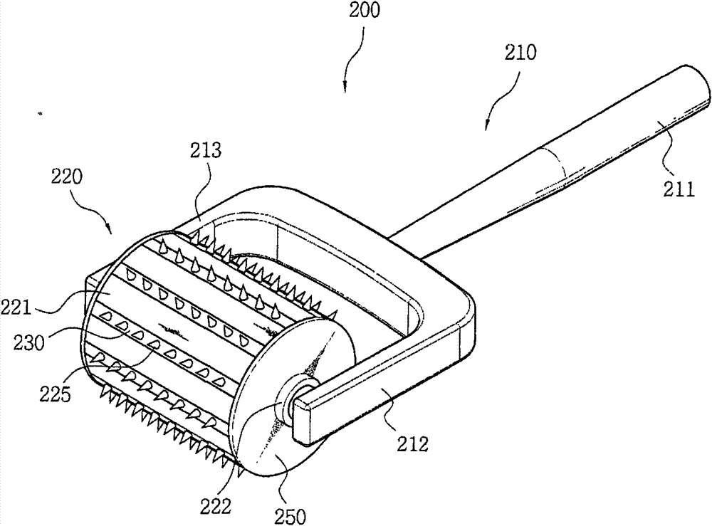
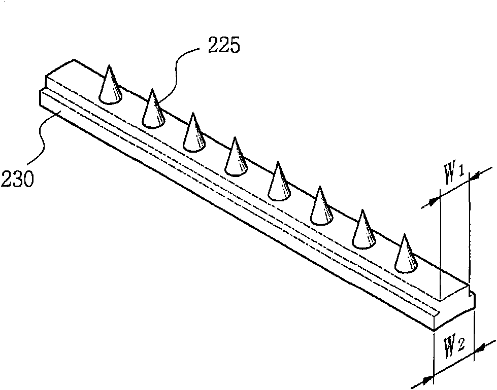
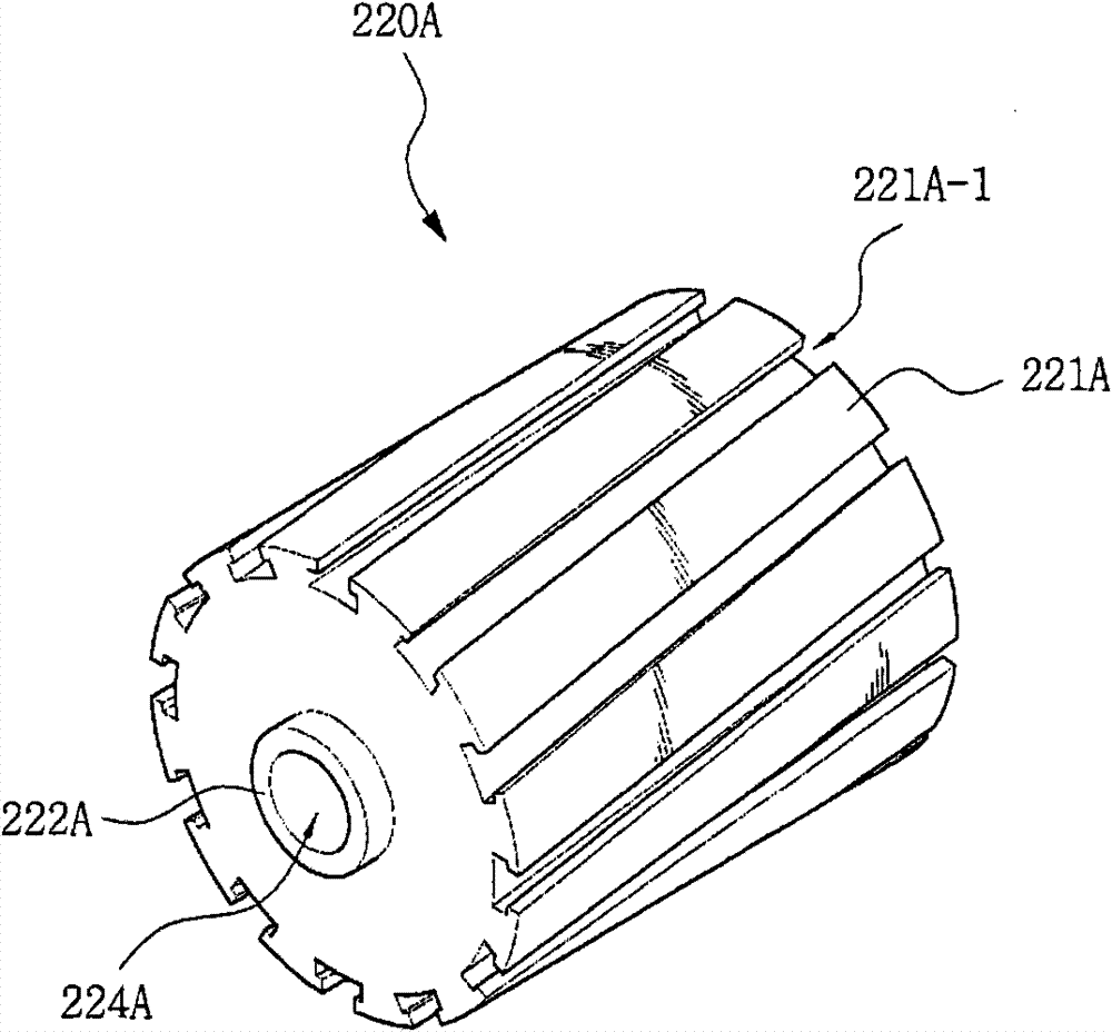
[0069] image 3 and Figure 4 are a perspective view and an exploded perspective view of a micro needle roller assembly according to a second embodiment of the present invention, showing structures of respective members constituting the micro needle roller assembly according to the second embodiment of the present invention.
[0070] refer to image 3 and Figure 4 , the micro needle roller assembly 200 (hereinafter referred to as “needle roller assembly”) also includes a roller head 220 and a handle member 210 .
[0071] The handle member 210 includes a handle 211 and first and second connection arms 212 and 213 extending from one end of the handle to both sides. Free ends of the first and second connection arms 212 and 213 correspond to both side ends of the inner member 222 of the roller head 220 . Cylindrical protrusions 212A and 213A having a certain length are protrudingly formed on the inner surfaces of the free ends of the first and second connecting arms 212 and 2...
no. 3 approach
[0100] A micro needle roller assembly (hereinafter referred to as "needle roller assembly") according to a third embodiment of the present invention will be described below.
[0101] Figure 7 is a perspective view of a needle roller assembly according to a third embodiment of the present invention, the needle roller assembly 300 according to the third embodiment of the present invention also includes a roller head 320 and a handle member 310 .
[0102] The structure and function of the roll head 320 in this embodiment are the same as those of the roll heads 220 and 220A according to the second embodiment, and thus a description thereof is omitted.
[0103] In addition, the structure and function of the needle 325 mounted on the roller head 320 in this embodiment is the same as that of the needle 125 mounted on the roller heads 120, 220 and 220A of the needle roller assemblies 100 and 200 according to the first and second embodiments. The structure and function are the same a...
PUM
 Abstract
Description
Claims
Application Information
 - R&D
- Intellectual Property
- Life Sciences
- Materials
- Tech Scout
- Unparalleled Data Quality
- Higher Quality Content
- 60% Fewer Hallucinations
Browse by: Latest US Patents, China's latest patents, Technical Efficacy Thesaurus, Application Domain, Technology Topic, Popular Technical Reports.
© 2025 PatSnap. All rights reserved.Legal|Privacy policy|Modern Slavery Act Transparency Statement|Sitemap|About US| Contact US: help@patsnap.com


