
Off-course driving device of non-off course gear used for aerogenerator

A technology of yaw driving device and wind power generator, which is applied in the control of wind power generators, wind power generators, wind power generation, etc. It can solve the problems of low power generation efficiency, low yaw precision, and many actuators, and achieve the improvement of yaw precision. , Improve system reliability and reduce noise

Inactive Publication Date: 2009-07-08
HARBIN INST OF TECH +1
View PDF0 Cites 17 Cited by
  • Summary
  • Abstract
  • Description
  • Claims
  • Application Information

AI Technical Summary

Problems solved by technology

[0005] In order to solve the problems that existing yaw driving devices on wind power generators have many actuators, poor reliability, and low yaw accuracy, which lead to reduced power generation efficiency, the present invention further provides a yaw-free gear for wind power generators yaw drive

Method used


Image

  • Off-course driving device of non-off course gear used for aerogenerator
  • Off-course driving device of non-off course gear used for aerogenerator
  • Off-course driving device of non-off course gear used for aerogenerator

Examples


specific Embodiment approach 1

[0009] Specific implementation mode one: as Figure 4~5 As shown, the yaw driving device without yaw gear on the wind power generator described in this embodiment includes a yaw main shaft 40, and the yaw driving device also includes a closed oil tank 20, a frequency conversion motor 21, a shaft coupling device 22, two-way quantitative pump 23, oil supply valve assembly 24, two-way hydraulic lock 25, low-speed high-torque hydraulic motor 26 and manual cut-off valve 27, frequency conversion motor 21 is connected with two-way quantitative pump 23 through coupling 22, and two-way quantitative pump 23 and the low-speed high-torque hydraulic motor 26 form a closed circuit 30, the oil supply valve assembly 24 is connected in parallel on the closed circuit 30 and communicates with the closed oil tank 20, and the two-way hydraulic lock 25 is connected in series on the closed circuit 30, The manual cut-off valve 27 communicates with the high and low pressure cavity of the low-speed hig...

specific Embodiment approach 2

[0010] Specific implementation mode two: as Figure 5 As shown, the yaw driving device in this embodiment also includes a yaw damper, and the yaw damper is composed of a hydraulic clutch 34, a pump 32, a motor 33, a proportional overflow valve 31 and an oil tank 35, and the hydraulic clutch 34 is installed On the shaft of the low-speed high-torque hydraulic motor 26, the inlet end of the pump 32 communicates with the oil tank 35, the hydraulic clutch 34 is connected with the outlet end of the pump 32, the pump 32 is connected with the motor 33, and the proportional relief valve 31 is arranged between the pump 32 and the hydraulic pressure. On the oil road between the clutches 34. In order to meet the power-off safety standards, a hydraulic clutch is installed on the low-speed high-torque hydraulic motor shaft as an emergency braking device. When the hydraulic system loses pressure, the hydraulic clutch acts to hold the hydraulic motor shaft tightly to achieve power-off safety....

specific Embodiment approach 3

[0011] Specific implementation mode three: as Figure 5 As shown, the replenishment valve assembly 24 in this embodiment is composed of two plug-in hydraulic control check valves 24-1. Other compositions and connections are the same as those in Embodiment 1 or 2.


PUM


Abstract

The invention relates to a deviation driving device without a deviation gear for a wind driven generator. The invention relates to a deviation driving device. The invention solves the problems that the prior deviation driving device on the wind driven generator has more executive elements, poor reliability and low deviation accuracy, thereby bringing about the low power generation efficiency. A frequency conversion motor (21) is connected with a two-way constant delivery pump (23) through a coupling (22); a closed loop circuit (30) is formed between the two-way constant delivery pump (23) and a low speed great torque hydraulic motor (26); an oil replenishing valve assembly (24) is connected in parallel on the closed loop circuit (30) and is communicated with a closed oil can (20); a two-way hydraulic lock (25) is connected in series on the closed loop circuit (30); a manual stop valve (27) is communicated with high and low pressure cavities of the low speed great torque hydraulic motor (26) and the closed oil can (20); and motor rotor (26-1) on the low speed great torque hydraulic motor (26) is fixedly arranged on a deviation main shaft (40). The deviation driving device has the advantages of good reliability, simple structure, low cost, stepless deviation velocity regulation, and the like.

Description

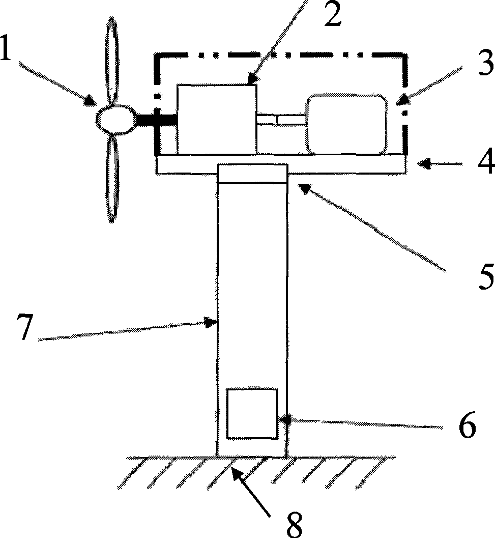
technical field [0001] The invention relates to a yaw driving device, in particular to a yaw driving device without a yaw gear used on a wind power generator, and belongs to the technical field of wind power generation equipment. Background technique [0002] At present, commercial large-scale wind turbines are generally horizontal axis wind turbines, such as figure 1 As shown, it is composed of a wind wheel 1, a speed-increasing gearbox 2, a generator 3, a nacelle 4, a yaw device 5, a control system 6 and a tower 7 and other components. The function of the wind wheel is to convert wind energy into mechanical energy. It consists of blades with excellent aerodynamic performance (currently commercial units generally have 2 to 3 blades) mounted on the hub. Acceleration, transfer power to generator. The above-mentioned components are all installed on the plane of the nacelle, and the whole nacelle is lifted by a tall frame. Since the wind direction changes frequently, a yaw sy...

Claims


Application Information

Patent Timeline
Patent Type & Authority Applications(China)
IPC IPC(8): F03D7/02
CPCY02E10/723Y02E10/72
Inventor 苏文海陈建华姜继海万保中刘庆和朱亮
Owner HARBIN INST OF TECH
Learn More